Signed Arithmetic Calculator with 2-digit display
Welcome to the Capstone Project! In Modules 4 and 5, you learned how to build basic binary calculators, represent signed numbers using 2's complement, and explore the internal architecture of Arithmetic Logic Units (ALUs).
Now it is time to bring everything together and build your final masterpiece: a Signed Calculator.
Every module in this course ends with a project, but this capstone is different. Instead of providing step-by-step wiring instructions or detailed schematics, you will act as a true hardware engineer. You must design the architecture, plan the logic paths, and troubleshoot the system yourself using the principles you have mastered throughout the course.
1) Data Representation and Conversion
Recall from Exercise 5.2 that while 2's complement is fantastic for hardware addition, it is not intuitive for human users. Humans prefer sign-magnitude format (a sign bit followed by the absolute value).
For this project, your calculator must be user-friendly. This means your input switches will represent numbers in sign-magnitude form. However, your internal adder circuits operate correctly only when using 2's complement representations.
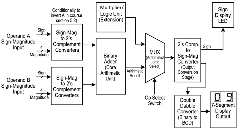
Therefore, your architecture will need data conversion stages:
- Input converters: Logic to conditionally convert sign-magnitude switch inputs into 2's complement before they reach the main adder.
- Output converters: Logic to take the 2's complement result from the adder and convert it back into sign-magnitude so it can be easily displayed.

1100 in a 4-bit system) into your calculator, what must your input converter stage feed into the core adder?
2) Handling Overflow
Because your calculator works with a fixed number of bits, arithmetic operations that exceed the available range will cause an overflow. Review your notes on overflow detection from Exercise 5.2.
Your calculator should cleanly handle or at least indicate when an operation exceeds the bit-width of your system. Remember that in 2's complement arithmetic, an overflow occurs if the carry-in to the Most Significant Bit (MSB) is different from the carry-out of the MSB.
3) Displaying the Result
Your final result must be shown in a human-readable format.
You will need to use the Double Dabble binary-to-decimal converter from Exercise 4.2 to process your final magnitude. Then, route that decimal data to 7-segment displays using the decoders you built in Project 3.
Additionally, you must dedicate an LED or a specific segment of a display to indicate the negative sign. This requires extracting the final sign bit from your output conversion stage.
4) Implementation and Extra Challenges
This is your blank canvas.
Minimum Requirements for Evaluation:
- Accept two multi-bit inputs in sign-magnitude format via switches.
- Output the correct mathematical result in decimal on 7-segment displays.
- Support both addition and subtraction purely by accepting positive or negative inputs.
- Clearly indicate if the result is negative using a dedicated LED or display segment.
Suggested Extensions (For extra challenge!): If you want to push your engineering skills further, do not stop at arithmetic. You can expand your circuit into a full Logic Unit. By adding Quad AND, OR, NOT, and XOR gate ICs in parallel with your adder, and using a multiplexer, you can create a system that selects between arithmetic operations and bitwise logical operations—just like the 74181 ALU you studied in Exercise 5.4!
Never build the entire circuit at once. Design your architecture on paper first. Build the system in modules (Input Conversion → Adder Core → Output Conversion → Display). Thoroughly test each module independently with test inputs before connecting them all together.
Congratulations on completing the course! You have journeyed from basic Boolean logic to designing a complete, functional computational machine.