Ripple Carry Adder
1) 4-Bit Ripple Carry Adder
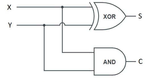
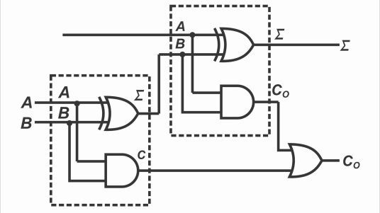
A single Full Adder calculates one column of numbers. To add two 4-bit numbers (like 1011 + 0110), we need to chain four Full Adders together.
The Ripple Effect
In this setup, the Carry Out of one adder becomes the Carry In of the next adder.
- Bit 0 (LSB): Adds the 1s column. Its C_{in} is connected to Ground.
- Bit 1: Adds the 2s column. It waits for the carry from Bit 0.
- Bit 2: Adds the 4s column. It waits for the carry from Bit 1.
- Bit 3 (MSB): Adds the 8s column. It outputs the final Overflow Carry.
Circuit Diagram
Build the Circuit
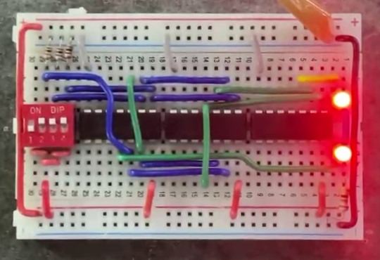
For this experiment, you are going to build the entire 4-bit calculator using only logic gates. This will be a complex build requiring careful wiring!
1. Build 4 copies of the Full Adder circuit you made in previous part.
2. Place them in a row on your breadboard(s).
3. Connect the Carry-Out of the first adder to the Carry-In of the second, and so on.
4. Connect the Carry-In of the very first adder to Ground (0V).
5. Connect 8xDIP switches for Number A (A0-A3) and 4 switches for Number B (B0-B3).
6. Connect 5 LEDs to the outputs (S0, S1, S2, S3 and Cout).
7. Connect all your DIP switches in 1kΩ pull down configuration, with bottom pins being constant High (5v).
8. Connect LEDs to ground through a 220Ω resistor.
9. Turn Power ON.

Submission
2) Miniaturization: The Adder IC
You probably noticed that building a 4-bit adder with individual gates uses a huge amount of wires and space. With so many connections, it is very easy to make a mistake!
In the real world, engineers rely on Integration. We can pack all those individual gates into a single chip (Integrated Circuit or IC), making the circuit smaller, faster, and more reliable.
The 74LS283
The 74LS283 is a 4-Bit Binary Full Adder IC. Inside this one small black chip are all the XOR, AND, and OR gates you just painstakingly wired up.
Key Features:
- Inputs: It accepts two 4-bit numbers (A_1-A_4 and B_1-B_4) plus a Carry In (C_0).
- Outputs: It produces a 4-bit Sum (S_1-S_4) and a final Carry Out (C_4).
- Power: It requires 5V (VCC) and Ground (GND) to operate.
- Speed: It performs the addition almost instantly, handling the "ripple" carry internally.
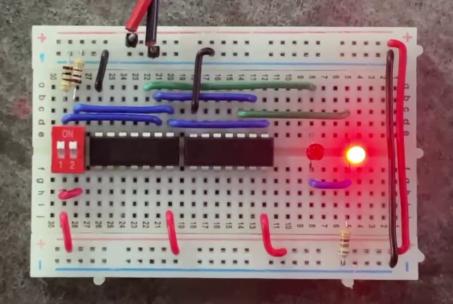
Build the Circuit
Now, let's build the clean version of the calculator using this chip.
1. Place the 74LS283 on the breadboard. Connect Pin 16 (VCC) to 5V and Pin 8 (GND) to Ground.
2. Connect the Carry In C0 pin (usually Pin 7) directly to Ground (To avoid floating input).
3. Connect your 8xDIP switches to the A and B inputs of the chip (A1-A4 and B1-B4).
4. Connect the Sum outputs (S1-S4) and the final Carry Out (C4) to your LEDs.
5. Connect all your DIP switches in 1kΩ pull down configuration, with bottom pins being constant High (5v).
6. Connect LEDs to ground through a 220Ω resistor.
7. Turn Power ON.
Final Submission
In the next module, you'll learn about an important binary decoder circuit called "Double Dabble", which will come to use in your final project of the module.