Signed Arithmetic
Signed binary arithmetic is one of the most interesting topics in the overall binary arithmetics section. It lays foundation to binary subtraction as we will learn in the coming sections. For now let's begin by trying to represent negative numbers using binary. Mind you, there are no symbols like +/- in computers. With the available number of bits, our task is to represent signed numbers and also do arithmetics with them.
1) Signed numbers representation in binary
So far, every of our dealing in binary arithmetics is unsigned. We never considered adding a positive and a negative number (or subtracting a number from the other). But if we want our calculator to operate on negative numbers as well, we need to figure out their representation and arithmetics. Let's start with representing negative numbers first. Primarily, negative numbers are represented in two ways - Sign-Magnitude and 2's complement.
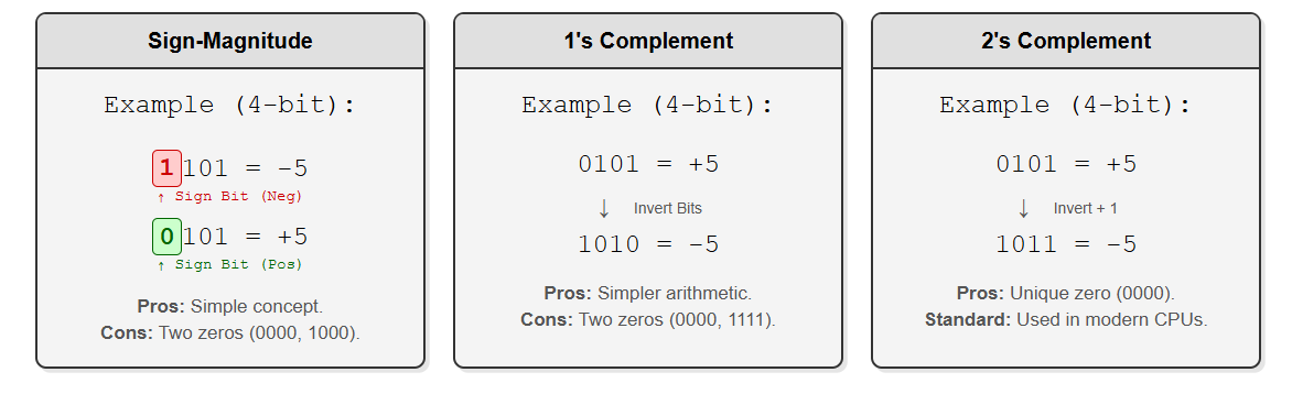
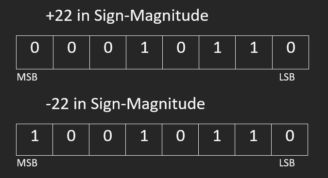
Sign-Magnitude Representation
This way of representation is relatively simple. Here, we assign the Most Significant Bit (MSB/First bit from left) as the 'Sign Bit'.
For example, in 4-bit calculations, -5 will be 1101 where the left most bit is 1 to represent a minus sign and the rest (101) represents the magnitude i.e. 5
Another example,
Note: From here onwards, we always talk about n-bit arithmetics where n is the fixed bit width of our circuits. Changing from a smaller bit width to a bigger one will require sign extension, about which we will discuss in the next section.

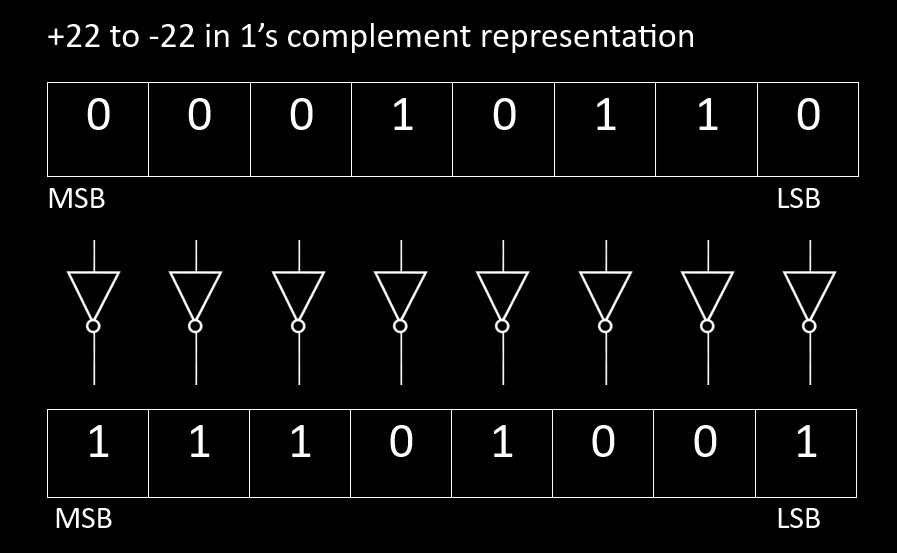
1's Complement
Before moving to 2's complement, let's start with 1's complement which is much simpler. 1's complement can also be used to represent negative numbers. 1's complement is obtained by simply inverting each bit of the number. For example, 17 in binary is 10001, and its 1's complement is 01110. Even here, the MSB represents the sign of the numbers.
There are some inherent issues with representing numbers using the above mentioned ways.
Firstly, in both the systems you have two ways of writing the number zero.
	* In 4-bit signed magnitude form, both 1000 and 0000 are zero.
	* In 4-bit 1's complement form, both 0000 and 1111 are zero.
Secondly, adding the negative of a number to itself
	* does not produce a zero in sign magnitude form.
	* produces all 1's in 1's complement form which complicates the arithmetics.
A more robust and computationally coherent way of representing signed numbers is 2's complement method.
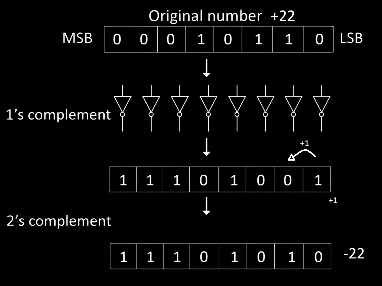
2) Two's complement
When we studied overflow in the accumulator, we saw a curious behavior: once a 4-bit result went past 15, the stored value suddenly wrapped around. For example, adding two numbers sometimes produced a result that looked like a + b − 16 instead of the true mathematical sum. This means our hardware silently “dropped” the extra bit because it had nowhere to store it. Now imagine choosing a second number so that the true answer should be 16—such as adding 3 and 13. In real math the result is 16, but in a 4-bit system the stored value becomes 0000. From the circuit’s point of view, adding 13 behaves exactly like adding −3. This wrap-around behavior is not a flaw—it is the key idea behind 2’s complement. In fixed-width binary systems, certain bit patterns are deliberately interpreted as negative numbers so that simple addition hardware can perform both addition and subtraction automatically, as we will learn in the next section.
* Two’s complement has a single, unique representation for zero which is 0000 (in 4-bit).
* The MSB still acts as the sign bit: 0 = positive, 1 = negative.
* A 4 bit 2's complement signed representation has a range of -8 to 7; in 8-bit, the range is -128 to 127.
* To negate a number, invert all its bits(1's complement) and add 1.
Activity: Try out adding a few numbers with their 2's complement by manually entering a number to one of the inputs in the adder and its 2's complement on the other input.
3) Two's complement generator circuit
Now let's make a circuit which generates 2's complement of the provided input bits.
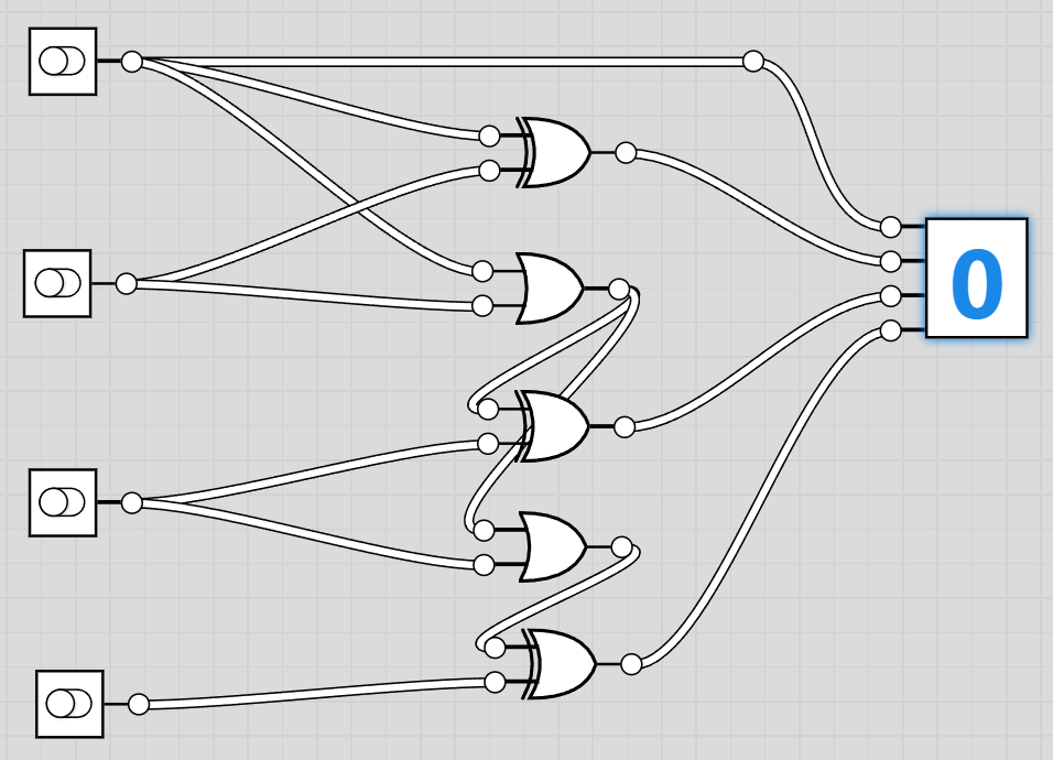
The schematic with logic gates below shows a way of making the 2's complement circuit with cascaded half adders.
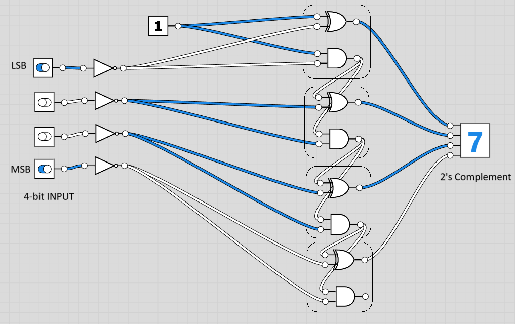
This version of it shows the implementation using a full adder circuit where we simply invert the inputs and Add a 1.
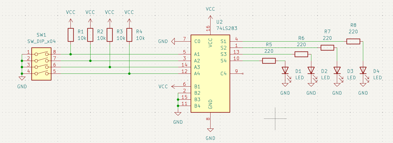
The following circuit is same as the previous one, but uses a quad XOR gate IC to implement conditional 2's complement generation.
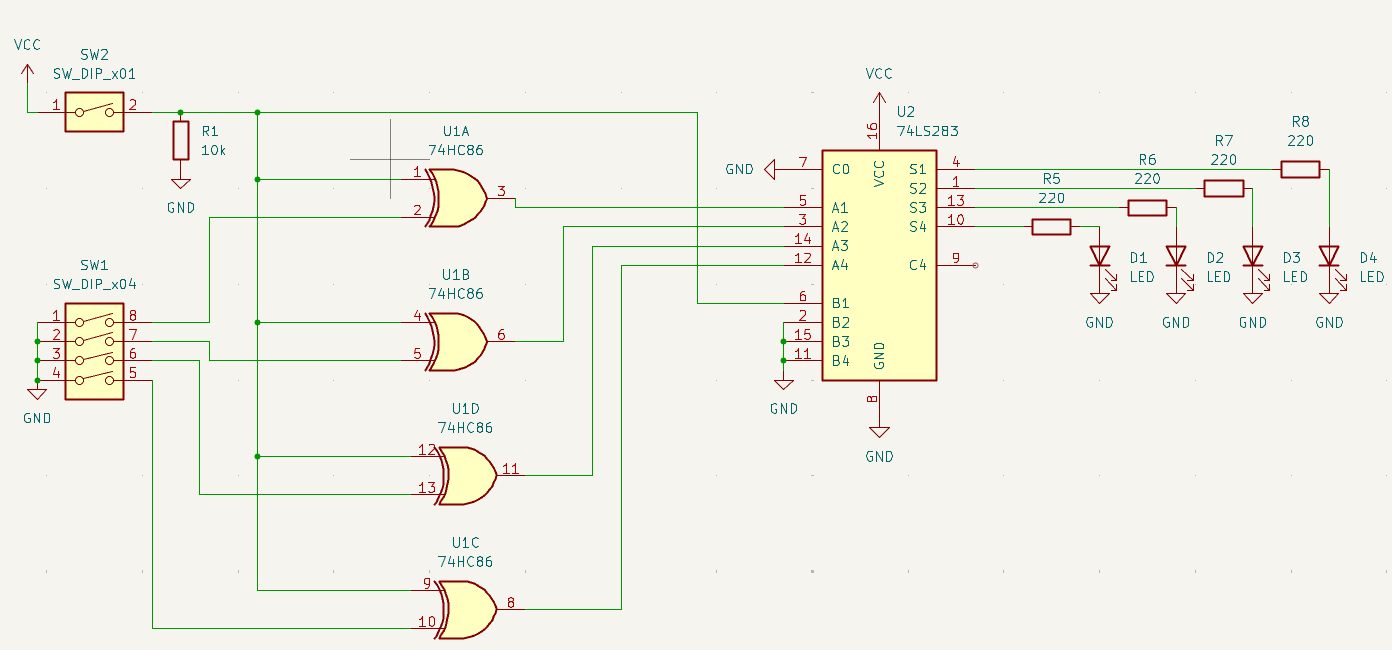
This circuit uses 3 XOR gates and 2 OR gates and is simpler to design.
Components You'll need:
- 1 × 74LS86 Quad XOR gate IC
- 1 × 74LS08 Quad AND gate IC
- 1 × 74LS32 Quad OR gate IC
- 1 × DIP Switch (4-bit input)
- 4 × 220 Ω resistors (for LED indicators)
- 4 × LEDs (optional, to show output bits)
- Jumper wires
- Breadboard
- 5 V power supply
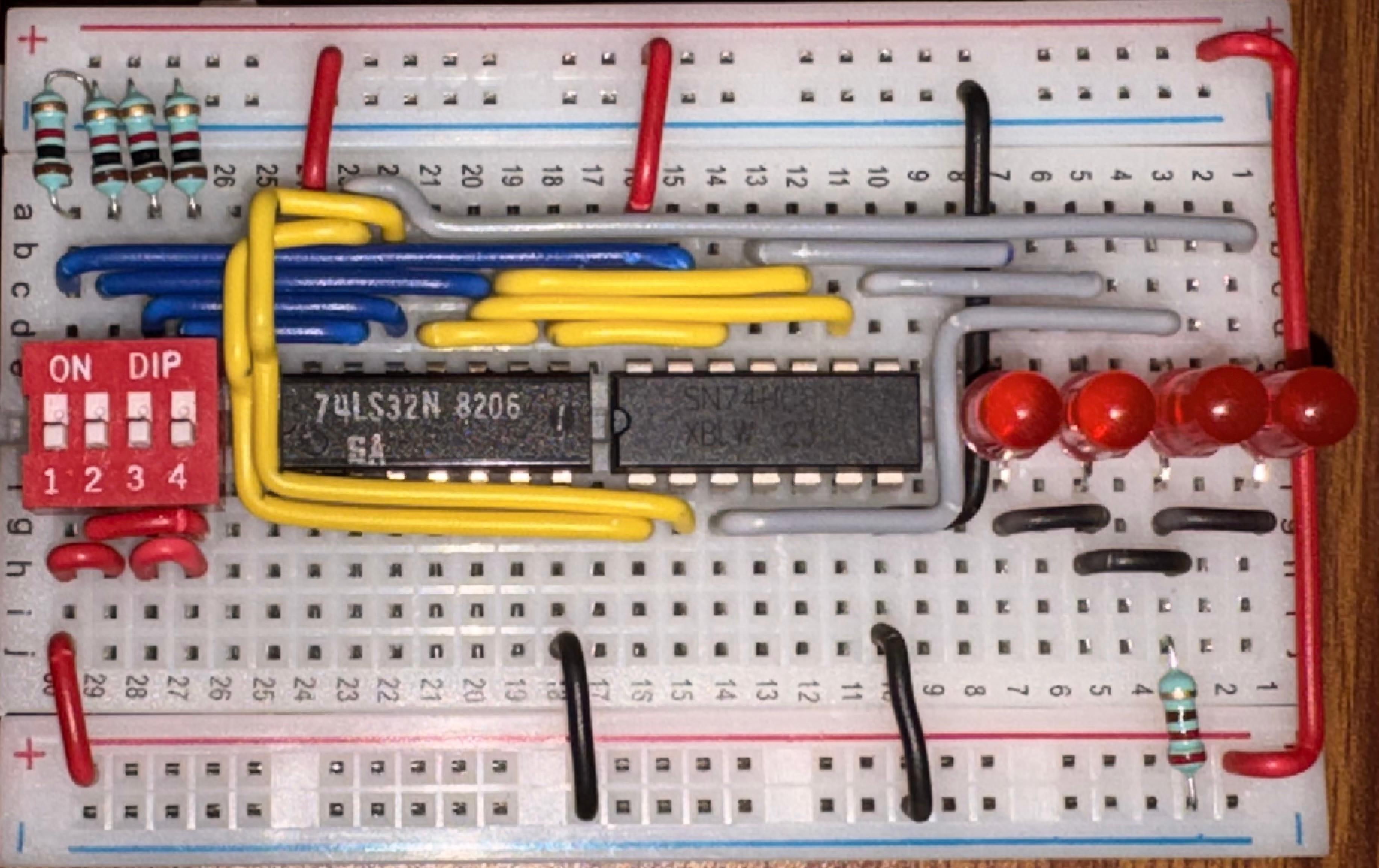
Step-by-step Assembly
1. With power OFF, place the 74LS86 (XOR), 74LS08 (AND), and 74LS32 (OR) ICs on the breadboard, each straddling the center gap.
   * Locate the notch or dot on each IC—this marks pin 1.
   * Pin numbers increase counter-clockwise around the package.

2. Power the ICs:
   * For all three chips:
     * Pin 14 → 5 V
     * Pin 7  → GND

3. Connect the 4-bit input from the DIP switch:
   * Label the inputs A3 A2 A1 A0 (MSB to LSB).
   * Each switch output goes HIGH for logic 1 and LOW for logic 0.

4. Generate the 1’s complement using XOR gates:
   * Tie one input of four XOR gates permanently to logic HIGH (5 V).
   * Connect:
     * A0 → XOR0 input
     * A1 → XOR1 input
     * A2 → XOR2 input
     * A3 → XOR3 input
   * The XOR outputs are B0–B3 (inverted inputs).

5. Add the +1 using ripple-carry logic.
   LSB stage:
   * B0 and logic HIGH → XOR gate → output T0.
   * B0 and logic HIGH → AND gate → carry C1.

6. Second bit:
   * B1 and C1 → XOR gate → T1.
   * B1 and C1 → AND gate → intermediate carry.
   * Combine any parallel carry paths with an OR gate to form C2.

7. Third bit:
   * B2 and C2 → XOR gate → T2.
   * B2 and C2 → AND gate → intermediate carry.
   * OR the carry terms → C3.

8. MSB:
   * B3 and C3 → XOR gate → T3.
   * Final carry out can be left unconnected for 4-bit arithmetic.

9. (Optional) Connect LEDs with series resistors from each output T0–T3 to GND so you can observe the generated 2’s-complement result visually.

10. Double-check all wiring and power rails, then turn ON the supply.
    Try entering different numbers on the DIP switch and verify that the output corresponds to the 2’s complement of the input.
Note: Never short outputs directly to 5 V or GND—always go through LEDs or other loads with resistors when probing signals.
Sign Extension
2's complement based signed numbers have to be sign extended when shifting from a smaller number of bits to a higher number of bits to ensure that the arithmetics doesn't suffer in the process. In 2's complement representation, the sign of the number can be determined easily by examining the MSB of the number. If it's a 1, it's a negative number, and if it's a 0, it's a positive number. Let us take two numbers, say -4 and 6. The signed binary representations in 4-bit are 1100 and 0110 respectively. Now let's extend these to 8-bits. The number 6 can simply be extended with zeroes and the result would be 00000110, which is the same positive 6. But if we extend the -4 with just zeroes, the number becomes 00001100 which is 12. To fix this, we read the MSB of any number and fill the blank bits after extension with the MSB. i.e. -4 in 8-bit would become 11111100 which is indeed -4. This is really important because this could easily break arithmetics when moving from a small bit width to a bigger one.
Final Submission
In the next exercise, we will learn about more complicated arithmetic and logical operations in binary, and the circuitry for it.