ALU Basics
So far we have learned how to represent signed numbers in binary using 2's complement, and we have built a circuit that generates the 2's complement of an input for us.
Now in this section, we will figure out how to perform subtraction using the previously learned circuits, then how to choose between addition and subtraction, and finally understand the basics of an ALU.
With this, we will reach our goal of building our own signed calculator.
1) Binary Subtraction Using 2's Complement
In the previous section on signed arithmetic and overflow, we learned that when we add the 2's complement of a number to itself, we get a 0 in fixed-bit binary arithmetic as a consequence of overflow.
Now that we have a solid representation for negative numbers, let's try subtraction using the same adder circuit we built in the accumulator exercise.
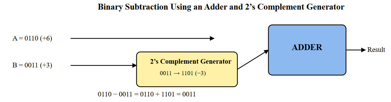
The 2's complement generator's output will be connected to one input of the adder circuit.
The other input of the adder receives the original number, and the output of the adder is stored in the register as before.
Together, the original input, the 2's-complemented input, and the adder form a complete binary subtractor.
Components you'll need:
- 1 × 74LS283 4-bit Full Adder IC
- Previously built 2’s complement generator circuit
- 2 × 4-position DIP switches (one for input A, one for input B)
- 8 × 10 kΩ resistors (pull-down resistors for DIP switches)
- 4 × LEDs (for displaying the result)
- 4 × 220 Ω resistors (current limiting for LEDs)
- Assorted jumper wires
- Breadboard and 5 V power supply
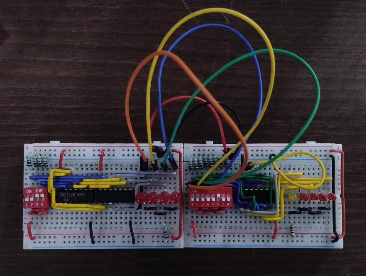
Step-by-step design:
1. With power OFF, place the 74LS283 adder IC on the breadboard so it straddles the center gap.

2. Power the adder:
   * Connect its VCC pin to the 5 V rail.
   * Connect its GND pin to the ground rail.

3. Set up the DIP switch for input A:
   * Connect one side of each of the four switches to 5 V.
   * From the other side of each switch, connect a 10 kΩ resistor to GND.
   * These four lines form bits A0–A3.

4. Connect the four input-A lines directly to the corresponding A inputs of the adder.

5. Set up the second DIP switch for input B in the same way:
   * One side of each switch to 5 V.
   * The other side pulled down to GND through 10 kΩ resistors.

6. Connect these four lines to the four inputs of the 2’s-complement generator circuit.

7. Connect the four outputs of the 2’s-complement generator to the B inputs of the adder.

8. Connect the four sum outputs (S0–S3) of the adder to four LEDs:
   * Each LED must be in series with a 220 Ω resistor.
   * Connect the resistor-LED chain to GND so that a HIGH output lights the LED.

9. Carefully check that:
   * Input A goes straight to the adder.
   * Input B only reaches the adder after passing through the 2’s-complement circuit.
   * All pull-down resistors are connected.
   * Power and ground rails are correct.

10. Turn the supply ON and test:
    * Choose values for A and B using the DIP switches.
    * Verify that the LED pattern corresponds to A − B.
    * Try multiple combinations to confirm correct subtraction.

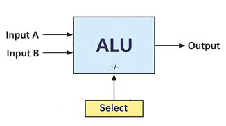
2) Introducing the Arithmetic Logic Unit (ALU)
In real processors, arithmetic operations such as addition and subtraction—and logical operations such as AND or OR—are grouped into a single block called the Arithmetic Logic Unit, or ALU.
Instead of building separate circuits for every operation, the ALU reuses hardware and selects the desired function using control signals.
In this section, we will study the ALU at a block-diagram level before implementing a simple version ourselves.
The ALU typically has two data inputs, a result output, and a set of control lines that decide which operation is performed.
These control lines are what allow the same internal circuitry to compute sums, differences, or logical results.
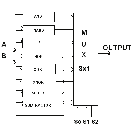
3) Selecting Operations Using a Multiplexer
To allow our circuit to either add or subtract, we need a way to choose between feeding the original input bits or their 2’s complement into the adder.
This selection is done using a multiplexer (MUX)—a digital switch that chooses one of several inputs based on a control signal, a concept first explored in Multiplexing.
In this section, we will:
- Insert a MUX before the adder input
- Add a control switch labelled ADD/SUB
- Observe how the same hardware performs two different operations
When the control line selects the direct input, the circuit performs addition.
When it selects the 2's-complemented input, the same adder automatically performs subtraction.
Components you'll need:
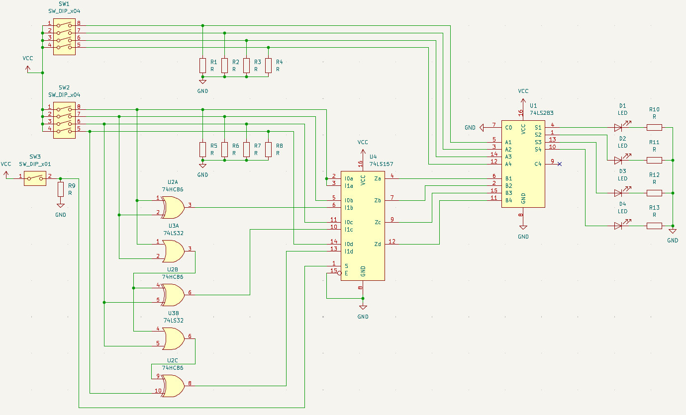
- 1x 74283 4-bit Binary Adder IC
- 1x 74157 Quad 2-to-1 Multiplexer IC
- Your previously built 2's Complement Generator circuit
- 2x 4-position DIP switches (for 4-bit inputs A and B)
- 1x 1-position DIP switch or tactile button (for the ADD/SUB control signal)
- 5x LEDs and 220Ω Resistors (for the 4-bit Sum and Carry Out)
- Breadboard & Jumper wires
Step-by-step design:
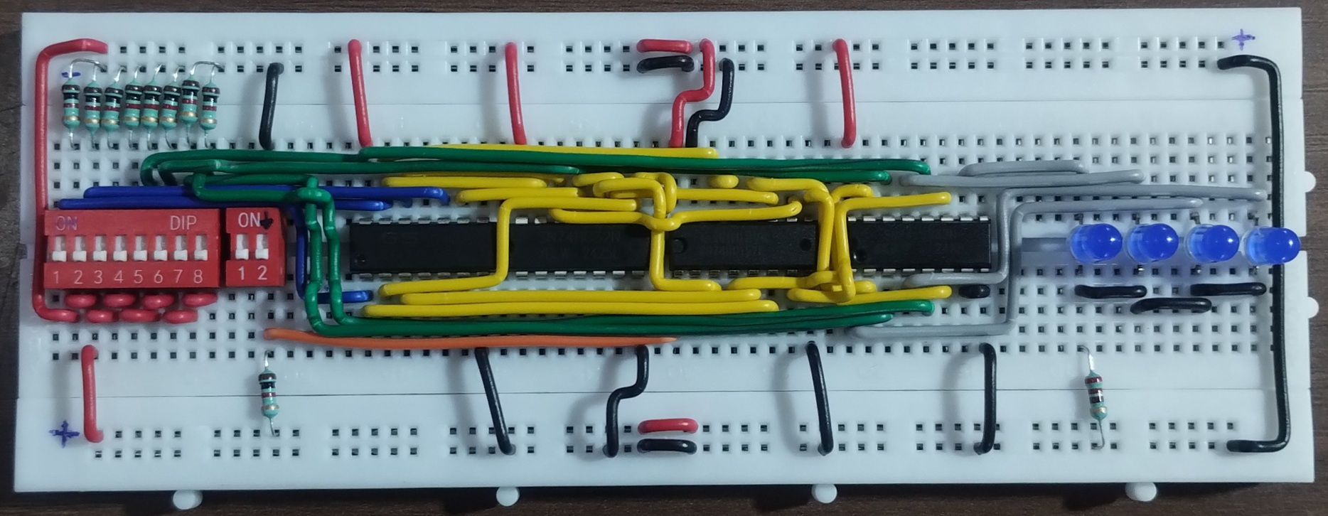
- Power & Ground: Place the 74283 Adder and 74157 MUX onto your breadboard alongside your existing 2's complement circuit. Connect VCC (Pin 16) to the 5V rail and GND (Pin 8) to the ground rail for both ICs.
- Enable the MUX: The 74157 has an Active-Low Enable pin. Connect Pin 15 (E') directly to Ground so the MUX is always active.
- Configure Input A: Connect your first 4-position DIP switch (Input A) directly to the A inputs of the 74283 Adder: A_1 (Pin 5), A_2 (Pin 3), A_3 (Pin 14), and A_4 (Pin 12).
- Configure Input B (The Split): Route your second 4-position DIP switch (Input B) to the inputs of your 2's complement generator circuit.
- Wire the MUX Inputs: * Connect the original raw B signals to the A data inputs of the 74157 MUX: Pins 2, 5, 11, and 14.
- Connect the 4-bit output from your 2's complement circuit to the B data inputs of the 74157 MUX: Pins 3, 6, 10, and 13.
- Wire the MUX to the Adder: Connect the four output pins (Y) of the 74157 MUX (Pins 4, 7, 9, and 12) to the B inputs of the 74283 Adder: B_1 (Pin 6), B_2 (Pin 2), B_3 (Pin 15), and B_4 (Pin 11).
- The Control Switch: Connect your ADD/SUB switch to the 5V rail with a pull-down resistor to Ground. Connect this signal to the Select pin (Pin 1) of the 74157 MUX.
- When LOW (0), the MUX passes the original B bits (Addition).
- When HIGH (1), the MUX passes the 2's complement of B (Subtraction).
- Outputs & Carry: Connect the Sum outputs of the 74283 (Pins 4, 1, 13, and 10) and the Carry Out (C_{out}, Pin 9) to your LEDs through 220Ω resistors. Tie the Carry In (C_{in}, Pin 7) to Ground.
- Test & Verify: Set Input A to
0101(5) and Input B to0010(2).- With the control switch LOW, your LEDs should output
0111(7). - Flip the control switch HIGH, and your LEDs should output
0011(3)!
- With the control switch LOW, your LEDs should output
What we built so far is the arithmetic part of a simple ALU, which is sufficient to make our own signed calculator. If we add logic gates to this and place in more multiplexers, we get a full fledged Arithmetic and Logic Unit.
Final Submission
In the next section, we will try to understand the working of an ALU IC - 74181.