Exercise 6.1: Accumulator
In previous section, you learnt about adder circuits, got an overview of binary arithmetics, and built your own 4-bit calculator! Now let's dive deeper into binary arithmetics. We begin by understanding what an accumulator is and how it works.

1) What is an Accumulator?
As the name sounds, accumulator stores values and keeps accumulating any incoming values. Think of a big tank of water with a water pipe connected. You send 2 liters of water first in a burst, then 3 liters, then 2 liters again. You'll end up with a total of 7 liters of water. Any more water you send will also end up getting added to the previous amount, and gets stored in the tank. To make a digital accumulator, we need a memory element that acts like the tank, and a pipe that makes the memory element accumulate incoming values to preexisting ones.
Register
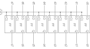
A register, as previously studied, is essentially a bunch of parallel flipflops which store bits when clock pin gets a pulse. Our goal is to accumulate values into this register. If we somehow are able to take the value from this register, and add it to the new value, and store the result back into this register, we get an Accumulator! The full 4-bit adder studied in the previous section can do the job for us, to design a 4-bit accumulator. Two such adders and Two 4-bit registers can be wired to make an 8-bit accumulator.
Circuit of an Accumulator
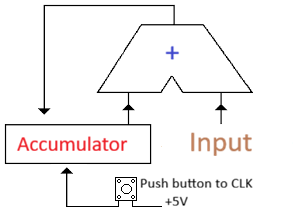
The outputs of the Adder circuit are connected to the inputs of the register bitwise, and the outputs of the register are connected to one of the inputs of the Adder circuit. The other input will be used to send in values to be accumulated. The clock pin of the accumulator will be connected to a push button which will connect the pin to 5V when pressed. The current value of register is added to the input value and presented at the output of the Adder. When the clock pin is pulsed, the latest result of the Adder is latched on to the register, and the same will be provided as one of the input of the Adder for the next press.
Note: The push button has to be debounced to avoid multiple increments in one press
2) Making your own Accumulator
Components You'll need:
- 1 x 74LS283 4-bit Adder IC
- 1 x 74LS173 4-bit Register IC
- 2 x Push buttons (For reset of register and clock pulse)
- 2 x 10kΩ resistor
- 2 × 10µF capacitor
- 1 x DIP Switch
- Double Dabble + 2 x 7-segment display setup
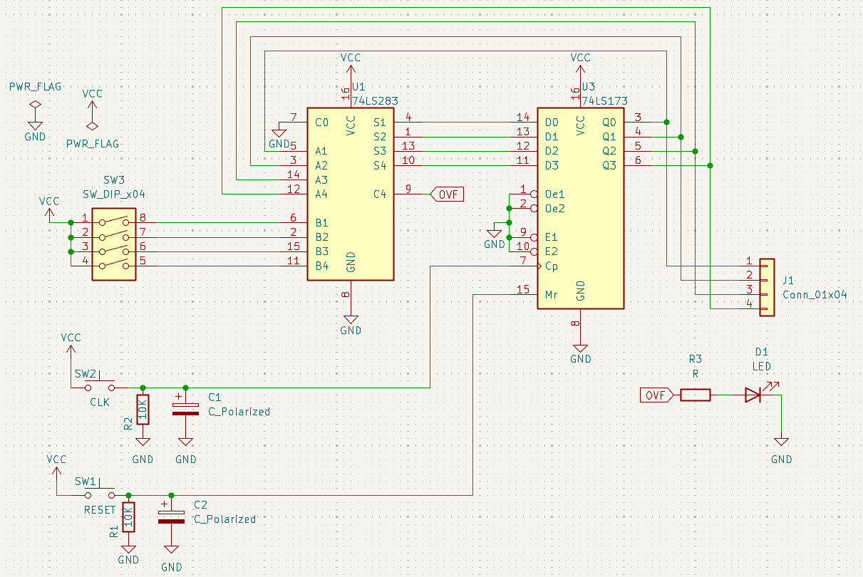
Step-by-step Assembly
1. With power OFF, place the 74LS283 adder IC and the 74LS173 register IC on the breadboard, each straddling the center gap.
   * Locate the small notch or dot at one end of the IC—this marks pin 1.
   * Pin numbers then increase counter-clockwise around the chip.

2. Connect power to both ICs:
   * 74LS283: pin 16 → 5 V, pin 8 → GND
   * 74LS173: pin 16 → 5 V, pin 8 → GND

3. Connect the register outputs to the adder inputs:
   * 74LS173 Q0 (pin 3) → 74LS283 A0 (pin 1)
   * 74LS173 Q1 (pin 4) → 74LS283 A1 (pin 4)
   * 74LS173 Q2 (pin 5) → 74LS283 A2 (pin 7)
   * 74LS173 Q3 (pin 6) → 74LS283 A3 (pin 10)

4. Wire the DIP-switch outputs to the other adder inputs:
   * DIP bit 0 → B0 (pin 2)
   * DIP bit 1 → B1 (pin 5)
   * DIP bit 2 → B2 (pin 9)
   * DIP bit 3 → B3 (pin 11)

5. Feed the adder’s sum outputs back into the register inputs:
   * S0 (pin 3) → D0 (pin 13)
   * S1 (pin 6) → D1 (pin 14)
   * S2 (pin 8) → D2 (pin 15)
   * S3 (pin 12) → D3 (pin 1)

6. Connect the register clock input (pin 11) to one push button.
   * Connect one side of the button to 5 V.
   * Connect the other side of the button to pin 11 of the 74LS173.
   * Add a 10 kΩ pull-down resistor from pin 11 to GND so the clock line stays LOW when not pressed.
   * Place a 10 µF capacitor across the push button terminals for basic debouncing.

7. Wire the register clear/reset input (pin 12) to the second push button.
   * Again use a 10 kΩ pull-down resistor to GND and a 10 µF capacitor across the switch.

8. Tie the register enable pins (pins 9 and 10) HIGH by connecting them to 5 V so the register always loads data when clocked.

9. Connect the four register outputs (pins 3–6) in parallel to the Double-Dabble input lines so the stored value is shown on the two 7-segment displays.

10. Carefully re-check every connection, confirm all power and ground rails are correct, then turn the supply ON and test by resetting the register and pressing the clock button while changing the DIP-switch inputs.
Note: Never tie an output pin directly to 5 V or GND, as this can create a short circuit and permanently damage the chips.

3) Overflow
Activity: Now, let's try to test the accumulator to its limits. Try setting the input number to 3 in binary using the DIP switch. Now reset the registers and press the button once. You'll see a 3 on the output which is expected. Now press once again and you'll see a 6. If you keep going on, you'll see 9, 12, and 15, and after this you'll notice the count goes back to 3 instead of further increasing. You can start with different numbers instead of 3, or even change the numbers between accumulations, and you'll still notice that the output value increases till a point and suddenly decreases. This is because of bit overflow.
Let's try to understand overflow better.
What is overflow?
Let's go way back to basics of numbers. Numbers are used to represent any kind of value. Numbers contain digits, and when you exceed the maximum possible value of a single digit, you move to a digit with a higher weight. The maximum value of a single digit is determined by its base. Example: digits in base-3 can be 0, 1, or 2 (3 numbers of digits, hence base-3). Theoretically, numbers can represent as large a value as needed. But in practical computing systems, you have limited digits to work with, as is the case in your adder where you only have a 2-digit display and 4-bit inputs/outputs. Let's try calculations with a fixed number of digits. Imagine you are asked to add two 2-digit numbers, e.g. 38 and 87, while fixing the output to 2 digits and not allowing any additional digits.
Adding the first 2 digits: 8 + 7 = 15. This cannot be represented using a single digit in base-10, so we carry the 1 to the next digit. The next 2 digits with a carry: 1 + 3 + 8 = 12. Here we run out of digits and cannot carry the 1 because of our 2-digit limitation.
This is, in essence, an overflow. Let’s try to understand the same idea in a binary context and finally observe it in hardware.
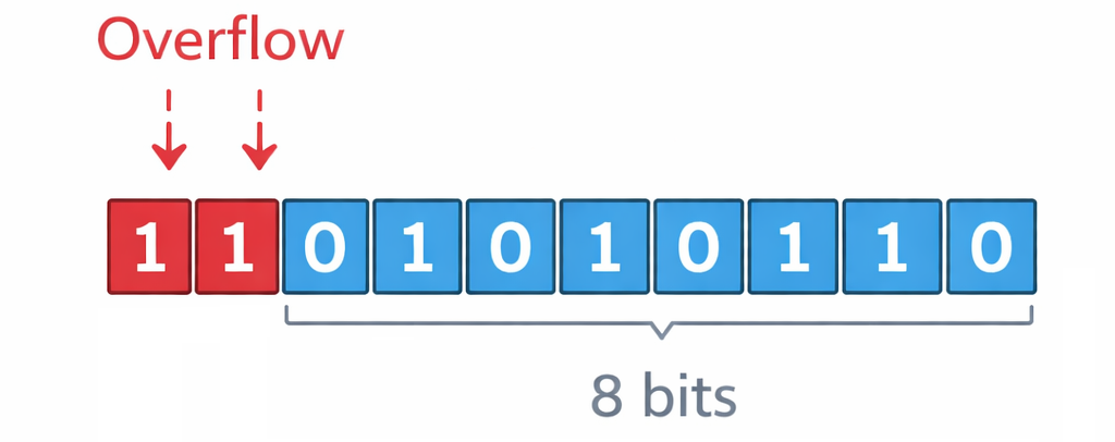
Overflow in binary
From the previous sections of binary arithmetic, you probably have a good idea of binary representations. Each bit can only be in 2 states and has 1 as its maximum value. Hence, n bits can represent 2ⁿ states — from 0 to 2ⁿ − 1.
For example: 6 in binary is 110 — requires at least 3 bits to represent 13 in binary is 1101 — requires at least 4 bits to represent 19 in binary is 10011 — requires at least 5 bits to represent
But in practical digital systems, the bit width (i.e. the number of bits that are operated upon) is always fixed in the hardware, similar to our adder which can only have operands with a maximum of 4 bits, and the result is also capped at 4 bits and a carry bit. In our 4-bit adder, if we try adding 6 and 13 (binary representations in the above example) we'd obtain 19 which, as previously mentioned, requires 5 bits. But our adder outputs only the first 4 bits which is its physical limit. Hence the output would be 0011 and 1 as the carry bit. This means the hardware is behaving exactly as designed, but the 4-bit result we observe is 3 because we have run out of bits to represent the true mathematical value.
Simply said, if we run out of enough bits to represent a number, it’s an overflow.
The significance of overflow will become more apparent in the next section on Signed Arithmetic. So, stick around!
INSERT PHOTO OF ACCUMULATOR ON BREADBOARD
Final Submission
In the next exercise, you'll learn about signed binary representation and using it for arithmetic opreations.