Up/Down Counter
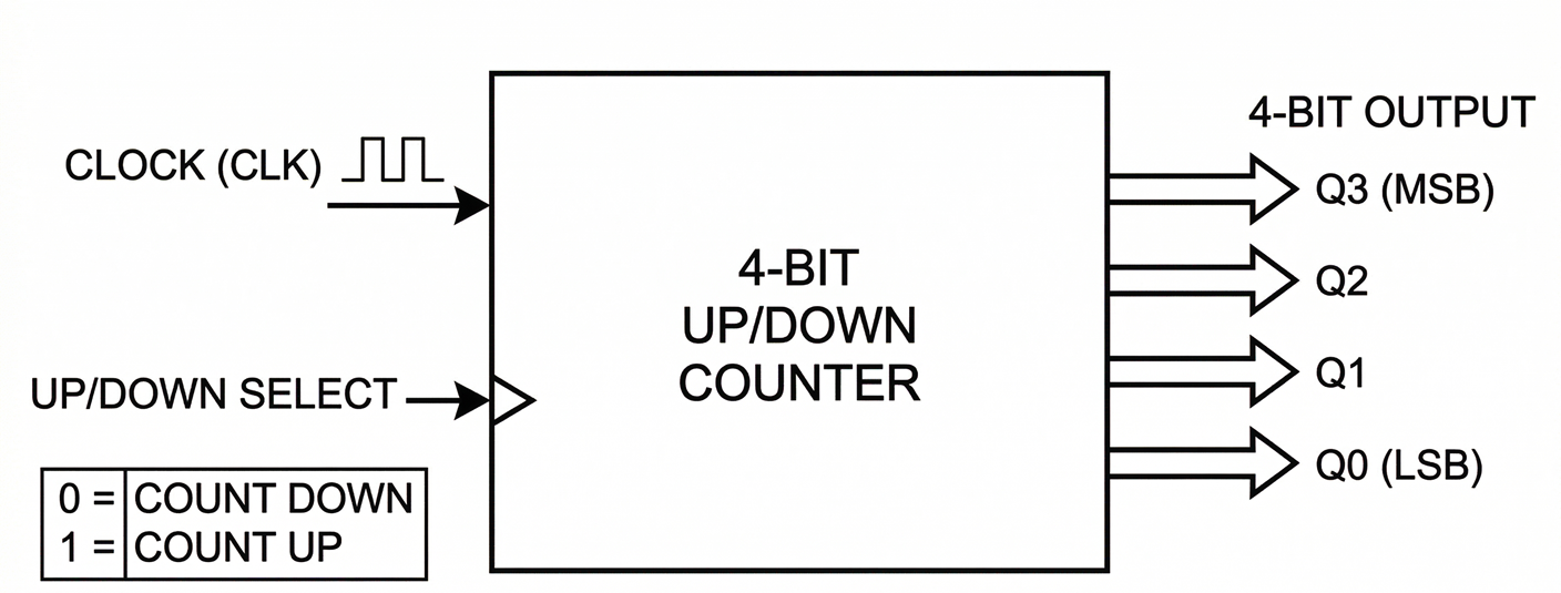
Welcome to the Module 2 Project! In Exercise 2.2, you learned how D flip-flops can be wired to toggle their state. Then, in Exercise 2.3, you cascaded these flip-flops to build a basic binary ripple counter. So far, your counters have only been able to count in one direction: UP (0, 1, 2, 3...). But what if you are designing a digital timer, a scoreboard, or an elevator tracking system? You need to be able to count backwards as well! In this project, you will design and build a 3-bit Asynchronous UP/DOWN Counter using 7474 D Flip-Flops and basic logic gates. By manipulating which signal serves as the clock for the next flip-flop, you can dynamically control the direction of the count with a single switch.
1) The Logic of Up and Down Counting
To understand how to make a counter go backwards, we need to review how positive-edge triggered ripple counters work.
In Exercise 2.3, you built a frequency divider using a 7474 D flip-flop.
You discovered that by connecting the inverted output (Q') directly back to the Data input (D), the flip-flop reads the opposite of its current state on every clock pulse.
This causes the flip-flop to continuously toggle its state (0 → 1 → 0 → 1), effectively cutting the clock frequency in half.
By cascading these frequency dividers—using the output of one flip-flop to clock the next—you created a binary ripple counter.
With this fundamental "toggle" behavior in mind, let's look at how the clock routing determines whether the counter counts UP or DOWN.
The UP Count
In a binary UP sequence (000, 001, 010, 011...), bit 1 must toggle exactly when bit 0 transitions from 1 to 0.
Since the 7474 requires a rising edge (a transition from 0 to 1) to trigger, we cannot use Q_0 directly as the clock for the next stage.
If Q_0 goes 1 → 0, its complement Q_0' goes 0 → 1.
- Conclusion for UP Counting: We must use the inverted output (Q') of the previous flip-flop to clock the next one.
The DOWN Count
Let's look at a binary DOWN sequence:
- 000 (0)
- 111 (7)
- 110 (6)
- 101 (5)
- 100 (4)
Notice that bit 1 toggles exactly when bit 0 transitions from 0 to 1!
Since our 7474 flip-flops trigger on a 0 → 1 transition, we can use Q_0 directly to clock the next stage.
- Conclusion for DOWN Counting: We must use the non-inverted output (Q) of the previous flip-flop to clock the next one.
To count UP, the clock for flip-flop N must come from Q'N-1.
To count DOWN, the clock for flip-flop N must come from QN-1.

2) Designing the Routing Logic
We need a circuit that acts like a railway switch. Based on a single control input (Let's call it U), we want to route either Q' or Q to the clock of the next flip-flop. Let's define our variables for a single stage connection:
- U = 1 (We want to count UP, so we want to route Q')
- U = 0 (We want to count DOWN, so we want to route Q)
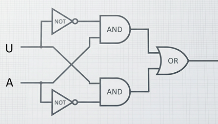
Using basic boolean logic, we can create an equation for the Clock Input (C_{next}) of the next flip-flop: C_{next} = (U \cdot Q') + (U' \cdot Q)
Let's trace this:
- If U = 1, then U' = 0. The equation becomes (1 \cdot Q') + (0 \cdot Q) = Q'. The next flip-flop receives Q' (UP count).
- If U = 0, then U' = 1. The equation becomes (0 \cdot Q') + (1 \cdot Q) = Q. The next flip-flop receives Q (DOWN count).
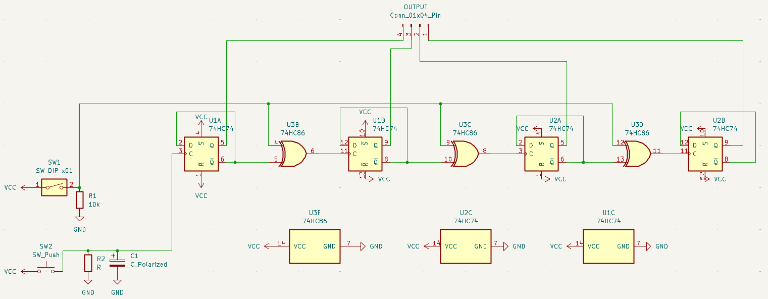
3) Hardware Implementation
It's time to build a 3-bit UP/DOWN counter! You will need quite a bit of breadboard real estate for this. Work methodically, keep your wires flat, and color-code your clock and logic signals.
Components You'll Need:
- 2x 7474 Dual D-Type Flip-Flops (Provides 4 flip-flops total; we only need 3)
- 1x 7486 Quad 2-Input XOR gate
- 1x Button (For your main counting clock)
- 1x DIP Switch (For your UP/DOWN control signal)
- 3x LEDs and 220Ω Resistors (To display your 3-bit output)
- Breadboard & Jumper wires
Step-by-Step Design:
Part 1: The Flip-Flops (The Counters)
- Power: Place all ICs on the breadboard. Connect VCC (Pin 14) to 5V and GND (Pin 7) to Ground for all logic chips.
- Setup Toggle Mode: For the three 7474 flip-flops you are using, connect their Q' output directly to their own D input. (e.g., connect Pin 6 to Pin 2, and Pin 8 to Pin 12).
- Preset/Clear: The 7474 requires its PRESET and CLEAR pins to be tied HIGH for normal operation. Connect pins 1, 4, 10, and 13 to the 5V rail.
- Main Clock: Connect your debounced push-button (from previous module) to the Clock input of the first flip-flop (Pin 3).
- Output LEDs: Connect the Q outputs of your three flip-flops to LEDs (with resistors) to display Bit_0, Bit_1, and Bit_2. Part 2: The Routing Logic (The Direction Switch) Now we must implement the logic C_{next} = U \oplus Q between the flip-flops using our 7486 XOR gate IC. You will need to build this logic block twice: once between FF0 → FF1, and once between FF1 → FF2.
- Control Signal: Connect one switch of your DIP switch to the 5V rail, with a pull-down resistor to ground. This is your U signal.
- First Routing Block (FF0 to FF1):
- Route the U signal into Pin 1 of the 7486 XOR IC.
- Route the non-inverted output (Q_0) of the first flip-flop into Pin 2 of the XOR IC.
- Connect the output of this XOR gate (Pin 3) directly into the Clock input of FF1.
- Second Routing Block (FF1 to FF2):
- Route the U signal into Pin 4 of the 7486 XOR IC.
- Route the non-inverted output (Q_1) of the second flip-flop into Pin 5 of the XOR IC.
- Connect the output of this XOR gate (Pin 6) directly into the Clock input of FF2.
4) Final Submission
Once everything is wired, power on your circuit.
- Set your UP/DOWN switch to
1(HIGH). Press your main clock button repeatedly. You should see the LEDs count up in binary:000, 001, 010, 011, 100... - Now flip your UP/DOWN switch to
0(LOW). Press your clock button. The LEDs should immediately reverse direction:...011, 010, 001, 000, 111...
Congratulations on finishing Module 2! You've learned how flip-flops store memory, how cascading them creates counters, and how combining sequential logic (flip-flops) with combinational logic (XOR gates) yields highly complex, controllable systems.
In Module 3, you will dive deeper into combinational logic design and learn how to make more interesting digital circuits.