Flip-Flops
1) Designing a D Latch: Solving the "Invalid State"
In our previous SR Latch (with Enable circuit), we had a small problem. We had to use two buttons (Set and Reset) to control one bit of memory. Even worse, if we accidentally pressed both buttons at once, the circuit entered a "forbidden state" where both outputs went High, breaking the logic that Q and Q' must be opposites.
We can fix this by ensuring that Set and Reset are always opposites.
If Set is 1, Reset must be 0.
If Set is 0, Reset must be 1.
And to store either of the states we use the Enable input we created.
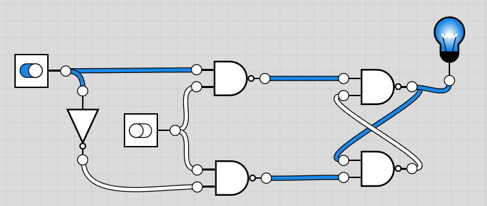
How do we do this? We use an Inverter (NOT Gate)! This new circuit is called the D Latch (Data Latch).
Hardware Setup: The 7404 Hex Inverter
To build this, we will add a new chip to our board: the 7404 Hex Inverter IC.

Components You'll Need
- Existing Circuit: Your Gated SR Latch (7400 IC)
- New Logic: 1x 7404 IC (Contains 6 Inverters)
- Input: 1x Push Button (Data)
Step-by-Step Assembly
- Place the 7404 IC: Insert the 7404 chip into the breadboard. Connect Pin 14 to VCC and Pin 7 to GND.
- Modify Inputs: Remove the old Set and Reset push buttons.
- Add Data Button: Place a new button (Data). Connect one side to VCC and the other to a 10k pull-down resistor.
- Connect to Set: Connect the Data button signal to the Set input of your NAND latch.
- Connect to Inverter: Connect the same Data signal to Pin 1 (Input) of the 7404.
- Connect to Reset: Connect Pin 2 (Output) of the 7404 to the Reset input of your NAND latch.
- Keep Enable: Ensure your Enable button is still connected to the latch's enable pins.
 The D Latch Logic
Now we have only one data input (D).
The D Latch Logic
Now we have only one data input (D). When **Enable is High**: The output Q copies input D.
When **Enable is Low**: The output Q is frozen (Memory).

2) From Latches to Flip-Flops
Connecting a Clock to a Latch creates a leaves the latch 'Transparent' to input data for all the time that the pulse stays HIGH. If there is any noise in the input data within this period, it gets propogated through the latch to the rest of the circuit.
We can solve this by making the Latches edge sensitive to clock, essentially turning them into a flip-flop. This means that the input Data is latched only on the edge of the pulse (Rising or Falling). A good analogy for this is given below:
- The Latch Way (Level Triggered): You leave the camera shutter open for a full second. If people move around during that second, your photo becomes a blurry mess. The output keeps changing as long as the shutter (Clock) is open.
- The Flip-Flop Way (Edge Triggered): The photo is captured right when the shutter button is pressed, and holding the shutter button does not have any effect on the image stored.
To fix this chaos, we need a device that takes a snapshot the exact instant the clock ticks. This brings us to the distinction between Latches and Flip-Flops.
| Feature | Latch (What we built so far) | Flip-Flop (The next step) |
|---|---|---|
| Trigger | Level Triggered Responds as long as Clock is HIGH. |
Edge Triggered Responds only at the instant the Clock goes from Low → High. |
| Analogy | Like Video Recording. | Like a Camera Snapshot. |
| Symbol | Usually a plain rectangle. | Rectangle with a small Triangle on the Clock pin. |
3) The 7474 IC: D Flip-Flop
Building flip-flops from NAND gates is great for learning, but messy for big projects. Engineers use dedicated chips. The most famous one is the 7474 Dual D Flip-Flop.

What makes the 7474 special?
- Edge-Triggered: It only updates memory when the clock goes from Low to High (Rising Edge).
- Preset and Clear: Special pins to force the memory to 1 or 0 instantly, ignoring the clock.
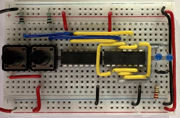
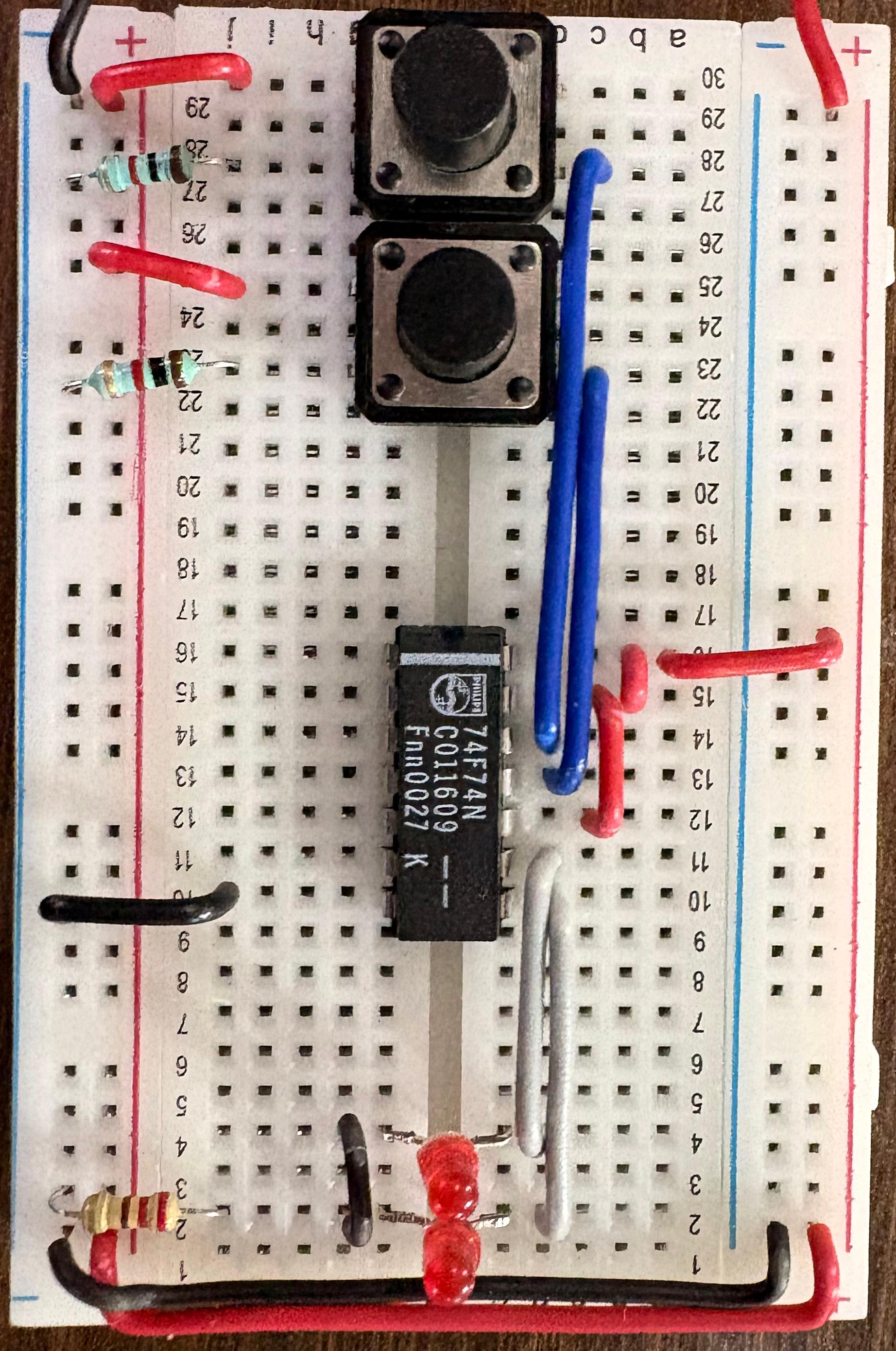
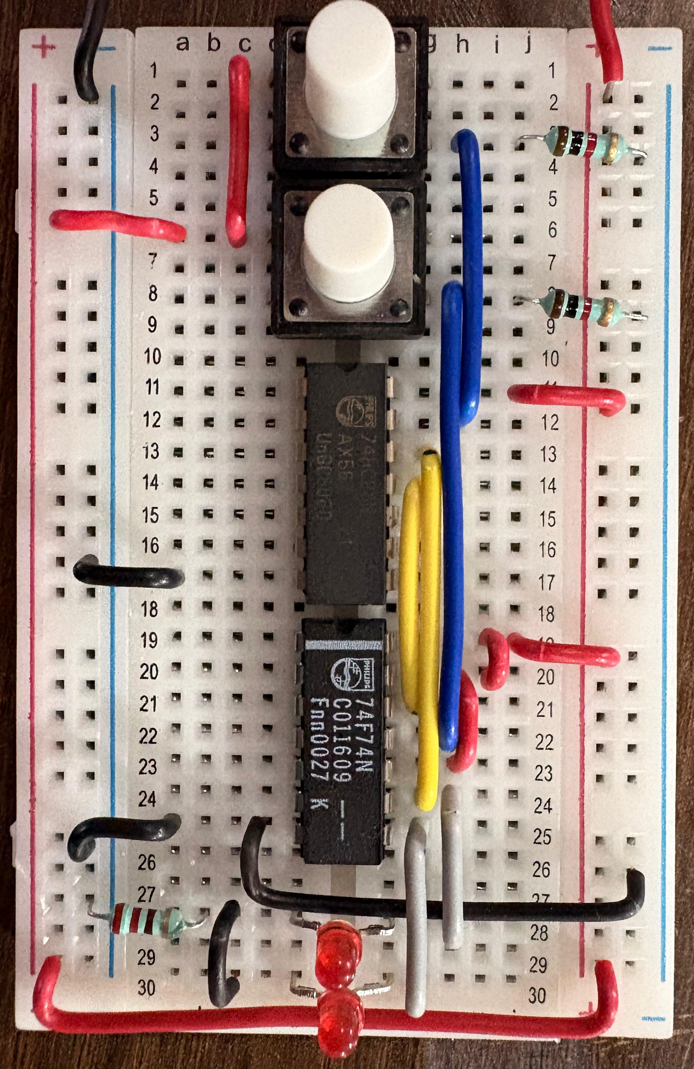
Components You'll Need
- 1x 7474 Dual D Flip-Flop IC
- 2x Push Buttons (Clock and Data)
- 2x LEDs (Red for Q, Green for Q')
Step-by-Step Assembly
- Power: Connect Pin 14 to VCC and Pin 7 to GND.
- Disable Overrides: Connect Pin 1 (CLR) and Pin 4 (PRE) directly to VCC (+5V).
- Note: These pins are "Active Low". If you leave them unconnected (floating) or ground them, the chip will get stuck.
- Inputs: Connect a button to Pin 2 (D) and another to Pin 3 (CLK).
- Outputs: Connect LEDs to Pin 5 (Q) and Pin 6 (Q').
Verification Experiment:
- Hold D button DOWN (Data = 1).
- Tap the CLK button. The Q LED should turn ON.
- Release D button (Data = 0).
- Tap the CLK button. The Q LED should turn OFF.
- The "Edge" Test: Hold D down, but don't press Clock. The LED should NOT change. It waits for the "rising edge" of the clock.
Refer to the datasheet of the D flip-flop IC and answer.
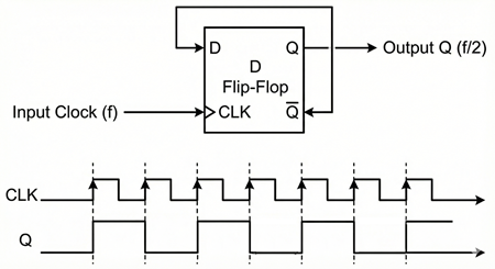
4) Building a Frequency Divider
Now for a cool trick. What happens if we make the Flip-Flop feed itself? By connecting the inverted output (Q') back to the input (D), the flip-flop will flip its state every single time the clock ticks.
Components You'll Need
- Your working 7474 circuit from the previous step.
Step-by-Step Assembly
- Remove the Data Button: Disconnect the button from Pin 2.
- Add Feedback Wire: Connect a wire directly from Pin 6 (Q') to Pin 2 (D).
- Test: Press the Clock button repeatedly. The LED should toggle On-Off-On-Off.
Why is this useful? If you tap the clock button 10 times per second, the LED will blink 5 times per second. You have just built a Frequency Divider (Divide-by-2 Counter)!
- Input Frequency (Clock): f
- Output Frequency (Q): f / 2
5) Final Activity: The T Flip-Flop (Toggle with Control)
The Frequency Divider we just built toggles forever. But what if we want to control whether it toggles or holds? We want a "Toggle Enable" switch. This is called a T Flip-Flop.
To do this, we need a controlled inverter. The XOR Gate (7486 IC) is perfect for this!
- XOR(A, 0) = A (Buffer / Hold)
- XOR(A, 1) = A' (Inverter / Toggle)
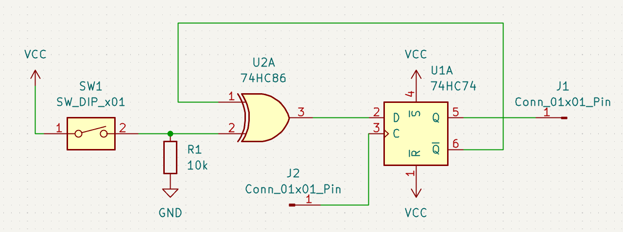
Components You'll Need
- Your 7474 D Flip-Flop
- 1x 7486 XOR Gate IC
- 1x Toggle Switch (This will be T)
Step-by-Step Assembly
- Place 7486: Insert the XOR chip and power it (Pin 14 VCC, Pin 7 GND).
- Feedback Logic: Connect Pin 5 (Q) of the 7474 to Input A (Pin 1) of the XOR.
- Control Logic: Connect your Toggle Switch (T) to Input B (Pin 2) of the XOR.
- Drive the D Input: Connect the Output (Pin 3) of the XOR to the D Input (Pin 2) of the 7474.
- Clock: Keep your Clock button connected to Pin 3 of the 7474.
Experiment:
- Set T = 0: Tap the clock. The LED should not change. (Hold Mode)
- Set T = 1: Tap the clock. The LED should flip at every other press. (Toggle Mode)
In the next exercise, we will chain multiple T Flip-Flops together to build the multi-digit counter, like the one used in our Digital Clock Project!