Binary Counters
1) Binary Counting: The Theory
We have built a T Flip-Flop that toggles between 0 and 1 every time the clock ticks. This is a 1-bit counter. But to count higher (0, 1, 2, 3...), we need more bits.
Let's look at the pattern of binary numbers:
- 00 (0)
- 01 (1) -> The 1s bit toggles.
- 10 (2) -> The 1s bit toggles back to 0, and the 2s bit toggles to 1.
- 11 (3) -> The 1s bit toggles.
The Golden Rule of Counting: Notice a pattern?
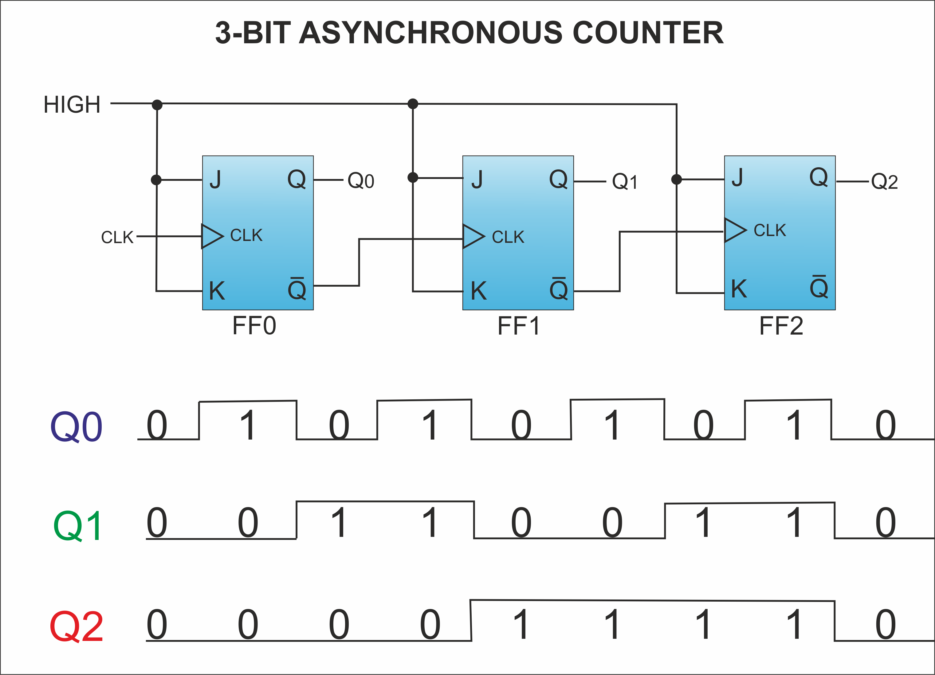
The 1s bit toggles on every clock pulse. The 2s bit only toggles when the 1s bit flips from 1 to 0. The 4s bit only toggles when the 2s bit flips from 1 to 0.
This "1 to 0" transition is a Falling Edge. If we connect the output of one flip-flop to the clock input of the next, we create a chain reaction. This is called an Asynchronous (Ripple) Counter.

2) Designing a 4-Bit Binary Counter
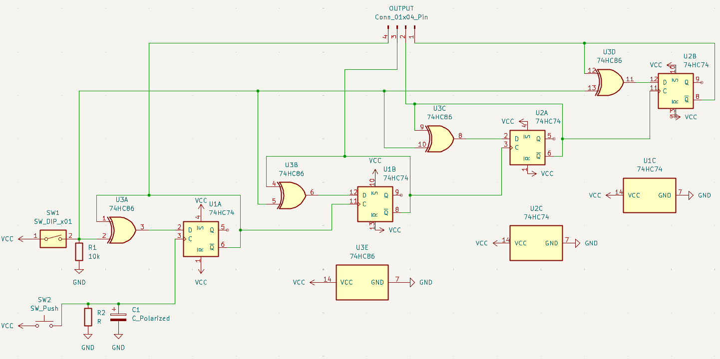
We will build a 4-bit counter using T Flip-Flops. Since we are using 7474 D Flip-Flops, we need to wire them as T Flip-Flops using XOR gates (like we did in the last section).
Why use XOR gates? This gives us a Count Enable switch. If Enable is 0, the XOR gates pass the current value back to D (Hold). If Enable is 1, they pass the inverted value (Toggle).
Hardware Components
- 2x 7474 Dual D Flip-Flop ICs (Total 4 Flip-Flops)
- 1x 7486 Quad XOR Gate IC (Total 4 XOR Gates)
- 1x 74LS48 BCD to 7-Segment Decoder (From Module 1)
- 1x 7-Segment Display (Common Cathode)
- 1x Push Button (Clock)
- 2x 10kΩ Resistors (One for current limiting and other for debouncing)
- 1x 10µF Capacitor (For debouncing)
- 1x Toggle Switch (Enable)
Wiring Strategy
We need 4 bits: Q0 (LSB), Q1, Q2, Q3 (MSB).
- The Enable Line: Connect your Toggle Switch to one input of all four XOR gates. This is your master "Count / Pause" switch.
- Bit 0 (Q0):
- Clock: Connect to your Push Button (Debounced).
- Feedback: Q0 -> XOR Input A. XOR Output -> D0.
- Bit 1 (Q1):
- Clock: Connect to Q0' (Not Q0) of the previous flip-flop.
- Note: Since 7474 is Rising Edge triggered, using Q' allows it to toggle when Q falls.
- Feedback: Q1 -> XOR Input A. XOR Output -> D1.
- Bit 2 (Q2):
- Clock: Connect to Q1' of the previous flip-flop.
- Feedback: Q2 -> XOR Input A. XOR Output -> D2.
- Bit 3 (Q3):
- Clock: Connect to Q2' of the previous flip-flop.
- Feedback: Q3 -> XOR Input A. XOR Output -> D3.
3) Connecting the Display
Counting with LEDs is fun, but reading binary "1011" is slow. Let's visualize it with a 7-segment display!
We will use the 74LS48 Decoder you used in Module 1.
Wiring Steps
- Place the 74LS48: Straddle the center gap. Power Pin 16 (VCC) and Pin 8 (GND).
- Connect Inputs:
- Connect Q0 (from Flip-Flop 1) to Input A (Pin 7) of 74LS48.
- Connect Q1 (from Flip-Flop 2) to Input B (Pin 1) of 74LS48.
- Connect Q2 (from Flip-Flop 3) to Input C (Pin 2) of 74LS48.
- Connect Q3 (from Flip-Flop 4) to Input D (Pin 6) of 74LS48.
- Connect Display: Wire outputs a-g to your 7-segment display pins (a-g). Don't forget the current limiting resistor on the Common Cathode (GND) pin!
Test It:
- Set Enable to 1.
- Press the Clock button.
- Does it count? 0, 1, 2, 3... 9.
4) Making a Decade Counter
The counter we made so far is capable of incrementing count at clock pulse. The counter counts all the way from 0 to 15 in binary. But for our BCD to 7-segment display decoder, we need to input between 0 (0000) and 9 (1001) for it to output valid numbers and avoid glitchy symbols. Refer to the datasheet of 7474 IC, and answer the question below.
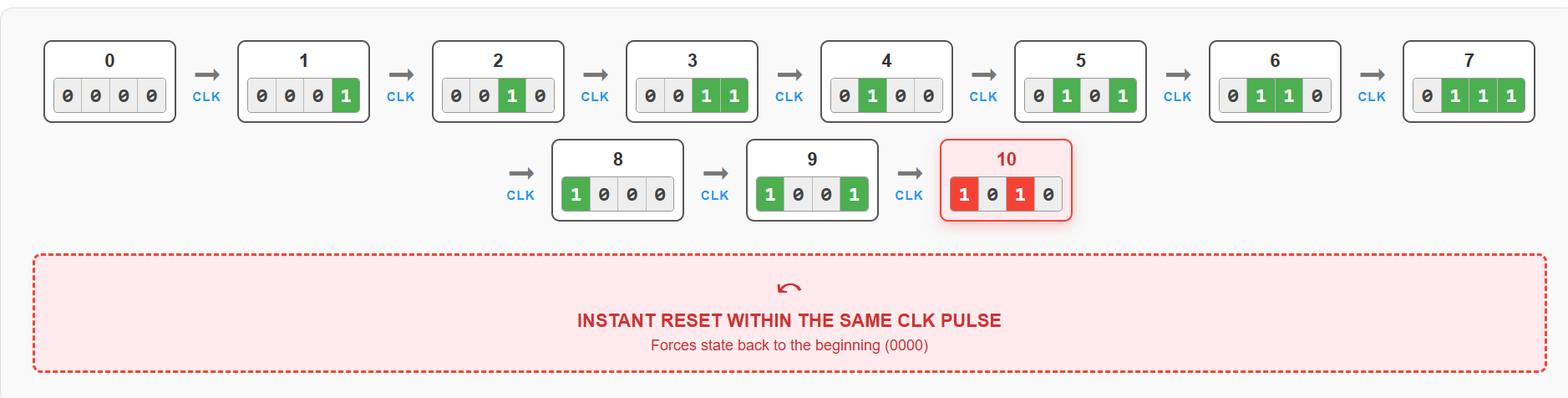
So if we reset the flip-flops once when they reach the count 10, they all reset to 0 and the subsequent clock pulse restarts the count from 0. The following will be the flow of the counter.
Activity: Wiring the Reset Logic
To make our counter stop at 9 and reset, we need to build a circuit that detects the number 10. In binary, 10 is 1010.
- Q3 (8s bit) is 1
- Q2 (4s bit) is 0
- Q1 (2s bit) is 1
- Q0 (1s bit) is 0
Notice that the number 10 is the very first time that both Q3 and Q1 are HIGH at the same time. If we monitor these two pins, we can trigger a reset exactly when the counter hits 10.
Since the CLR pins on our 7474 flip-flops are Active-Low (they need a 0 to reset), we need a gate that outputs a 0 only when both its inputs are 1. The NAND Gate does exactly this!
Components You'll Need
- Your existing 4-bit Binary Counter circuit (from the previous section)
- 1x 7400 Quad 2-Input NAND Gate IC
- Additional jumper wires
Step-by-Step Design
Step 1: Free the Clear Pins
In your previous 4-bit counter build, you connected the CLR pins (Pins 1 and 13 on both 7474 ICs) directly to VCC (5V) so they wouldn't reset randomly.
- Disconnect Pin 1 and Pin 13 on both 7474 chips from the VCC rail.
- Use jumper wires to connect all four of these
CLRpins together into a single "Master Reset" line on your breadboard.
Step 2: Add the NAND Gate IC
- Place the 7400 IC on your breadboard straddling the center gap.
- Connect Pin 14 to VCC (5V) and Pin 7 to GND.
Step 3: Wire the Detection Logic We will use the first NAND gate on the 7400 IC (Inputs on Pins 1 & 2, Output on Pin 3).
- Connect a wire from Q1 (Pin 9 of your first 7474 IC) to Pin 1 of the 7400 IC.
- Connect a wire from Q3 (Pin 9 of your second 7474 IC) to Pin 2 of the 7400 IC.
Step 4: Trigger the Reset
- Connect the output of the NAND gate (Pin 3 of the 7400 IC) to your "Master Reset" line (which connects to all four
CLRpins on your flip-flops).
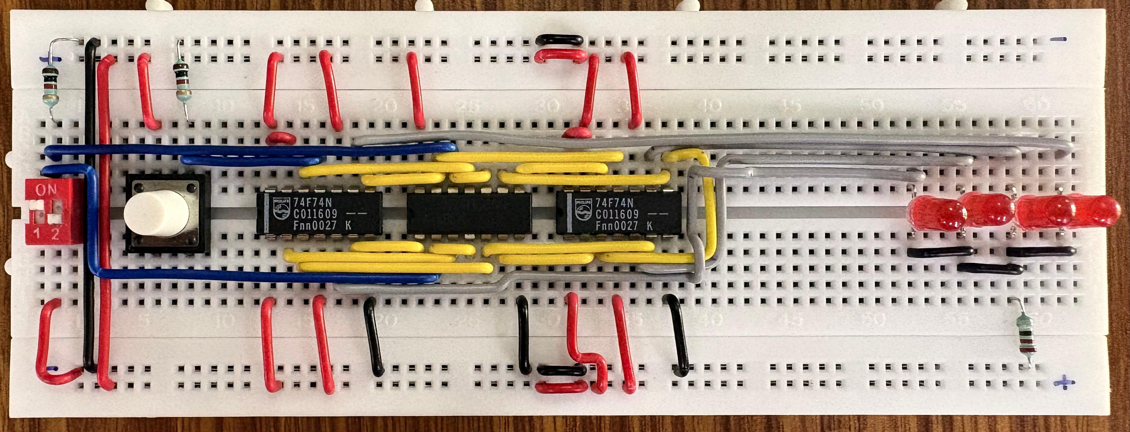
Test It Out! Turn on your power and pulse the clock button. Watch your 7-segment display (or LEDs). It should count: 0, 1, 2, 3, 4, 5, 6, 7, 8, 9... and on the next press, immediately snap back to 0! You have successfully built a Decade (Mod-10) Counter.
5) Understanding CD4026 IC
You have built a 4-bit counter from scratch! This is how engineers built computers in the 1960s. However, for our final digital clock, we will have to wire a lot of such flip-flops which can be tedious.
In Module 1, you used the CD4026 Decade Counter.
- The IC has a counter and a BCD to 7 segment display decoder built-in.
- The counter is automatically reset when it hits 10, making sure it only counts from 0-9.
- One IC can count till 9. To add an extra digit, the carry out pin of 1s digit can be connected to the CLK input of another such IC connected to a 7 segment display, which will act as the 10s digit. Same procedure can be used to extend the counter to 100s and so on.
The CD4026 IC is functionally similar to the circuit we made on breadboard so far. It can be used to replace all the gates, flip-flops and wiring we did and to design digital clocks.
In the next section, we will learn about a different application of D flip flops which is a register file, before heading towards our module project.