Counters
In the previous exercise, you learned how to use an IC chip to display numbers on a 7-segment display. Now, we will expand our setup to use our 7-segment display as a counter going from 0 to 9!
The exercises in this course build on each other with increasing levels of difficulty. Take a moment to make sure you have understood everything so far, and refer to the Resources page if you need any help!
1) CD4026B
The IC chip we have used so far is the DM74LS48N. However, that chip's functionality is limited to displaying the decimal number that corresponds to a given binary input.
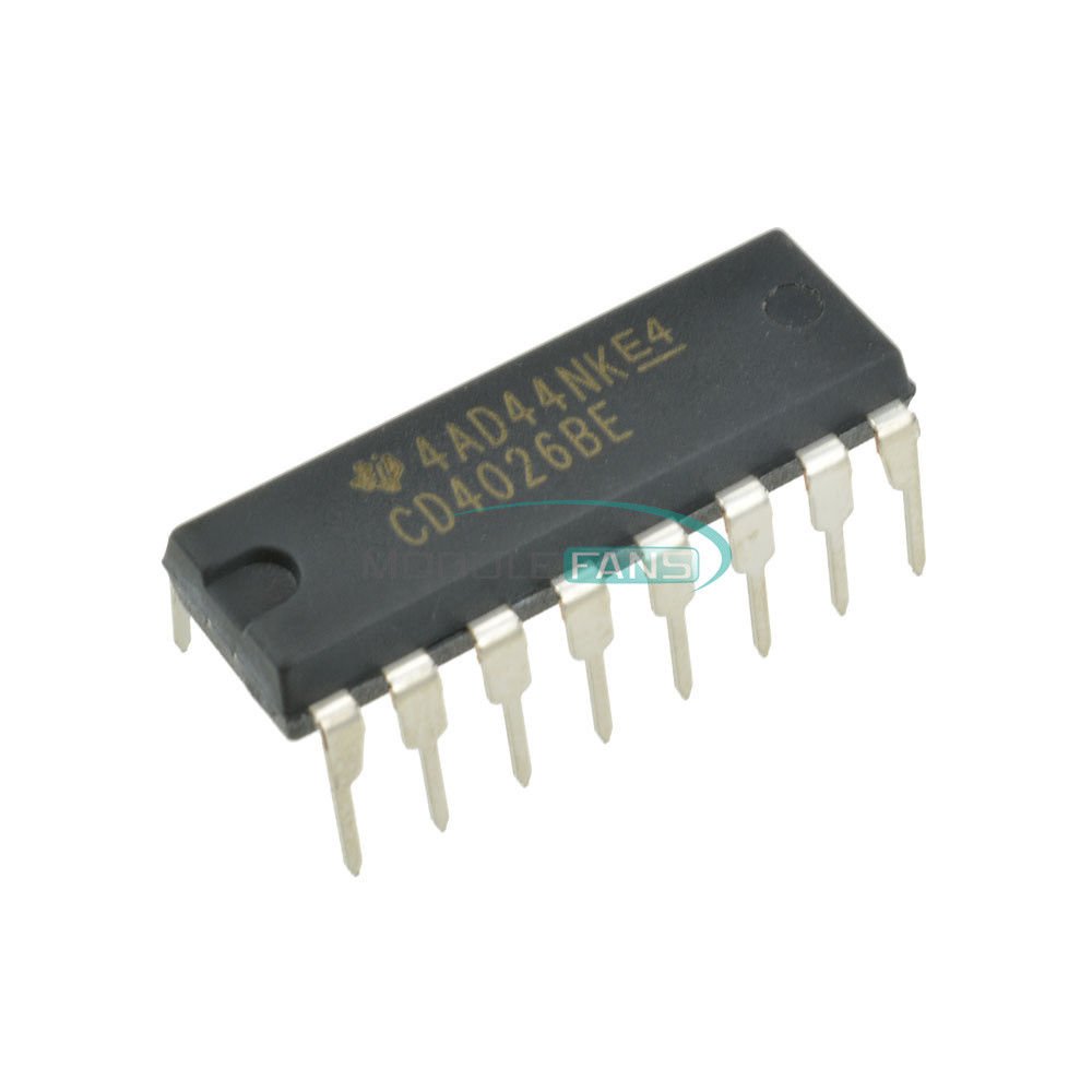
What if we want our setup to count, rather than displaying one number at a time? For this, we will need to use the CD4026B.
CD4026B
Last time, we gave you the pinout of the DM74LS48N chip for you to connect on your breadboard. A crucial step in working with hardware is reading datasheets, so this time, we will teach you to read one on your own!
Take a look at the CD4026B's datasheet.
It seems like a lot, but generally the first few pages of a datasheet will have all of the information you need for basic circuits. For now, we will focus on two main areas of a datasheet.
1. Functionality Overview
As soon as you open the datasheet, you should see a big paragraph of text. This paragraph describes the functionality of the IC chip in English, letting users understand how the IC chip works in theory.
2. Pinout
If you look lower down on the first page, or occasionally somewhere on the first few pages, you should see a pinout diagram of the IC chip that shows what signals the IC chip expects as inputs and what signals it will provide as outputs for proper functionality. To find the pinout diagram, look for a rectangular shape with labeled pins like the one below.


Now that we know how to find the CD4026B chip's pinout, let's go through the connections one at a time and understand what each of them means.
Input Pins: These are pins that allow us to give the IC chip information for it to function. Most ICs will have some input pins that are only needed for advanced functions, and can otherwise be left unconnected.
- VSS: This is a notation that pinout diagrams use for ground, which you are already familiar with. This pin should be connected to our GND rail.
- VDD: This is a notation that pinout diagrams use for the positive terminal. Generally, you should check the datasheet to see what voltage the component is expecting. For this IC, our 5V is fine.
- Clock: This is a common signal for many IC chips. Without a clock, how would the IC know how fast it should change to the next number? The counter increments every time the clock pin recieves a HIGH pulse, meaning our input signal goes from LOW to HIGH. Ignore this pin for now. We will come back to it later in the exercise.
- Clock inhibit: If this pin is connected to 5V, it will freeze the current number on the screen and block the clock signal. Ignore this pin.
- Display enable in: In order for anything to show up on our display, we must enable the display. We do this by connecting this pin to 5V. If this pin was connected to GND, our 7-segment would be empty, even though the chip may still be counting internally.
- Reset: If this pin is connected to 5V, it will reset the counter to 0. Ignore this pin for now. We will come back to it in this module's project.
Output Pins: These are pins that provide information from the IC chip which we can connect to other components. Not all of the output pins may be necessary for every project. We know that they are output pins by understanding the purpose of the chip (providing A-G segments) as well as looking for pins that end in "out".
- A-G: These pins correspond to the A-G segments of the 7-segment LED like we talked about in Exercise 1.2. Each individual pin will go HIGH (5V) whenever that segment should be on to display a specific number, and the pin will be LOW (0V) otherwise.
- Display enable out: This pin copies the value that is at display enable in. This is often used when we have multiple 7-segment LEDs that we are using together, and we want their displays to toggle between on and off in a complex manner at the same time. Ignore this pin.
- Carry out: This pin will go HIGH when the counter reaches 9, and will return to LOW when it rolls back to 0. This functionality can be used to tell another counter when it should increment. Ignore this pin for now. We will come back to it in this module's project.
- Ungated "C" segment out: This pin will correspond to the C segment of the 7-segment LED, but it ignores whether the display is enabled or not. This functionality can be useful for more advanced circuits. Ignore this pin.
2) Displaying Zero
Let's begin by getting the 7-segment LED to display zero.1. With your power OFF, remove your DM74LS48N chip, the DIP switch, and any extra jumper wires.
2. Connect your CD4026B across the center gap of the breadboard, and connect each of the pins as described in the instructions above. If an instruction says to ignore this pin, leave it unconnected.
3. Turn your power ON. At this point, you should see a zero appear on the 7-segment display!
If your 7-segment LED does not light, or does not look like a zero:
- Check your power connections.
- Check each of the IC connections using the multimeter.
- Check that you are connecting each A-G IC pin to the correct pins of the 7-segment LED.
- Make sure you have a 220Ω resistor connected from the GND of the 7-segment LED to your ground rail.
- If your circuit is still not working, try to mentally and physically walk through the circuit. Remember that your path should be a connected loop from the 5V power source -> components -> GND of power source.
3) Counting
Now, it's time to make our circuit count! Our first step is to understand how the display increments in the first place, and then to implement it in hardware.
Clock
The clock functionality is unique in that we need there to be a changing value (from LOW to HIGH) for the IC to register that it needs to increment the value on the display. These are known as pulses.
We can think of the clock as a square wave, where the value alternates between HIGH and LOW.

For now, we want to control when our display increments, so our goal is just to make transitions occur between LOW and HIGH on the clock pin. We will do this with a button!
Button

A button is a simple component that lets a person control a circuit by pressing it. When the button is pressed, it temporarily connects two points in the circuit, allowing current to flow. When the button is released, the connection is broken, preventing current from flowing.
On the button, we see there are four legs, with two pins of the button on one side and two pins on the opposite side. Each pair of pins opposite each other are internally connected, in such a way that each pin is disconnected from the closest pin to it.

When the button is pressed, the two sets of pins become connected, allowing current to flow between the yellow and pink sides.
1. With your power OFF, connect your button across the center gap of the breadboard. Make sure that the "yellow-colored" legs and "pink-colored" legs from the diagram earlier are on opposite sides of the center gap.
2. Connect one of the legs from one side of the button to 5V, and one of the legs from the other side to the clock pin of the CD4026B.
3. Turn your power ON. At this point, you should see a zero appear on the 7-segment display, and you should be able to increment your counter every time you click the button!
If your 7-segment LED does not increment:
- Check your button's orientation.
- Check what you connected each leg of the button to.
Note: You may see that your counter occasionally skips numbers even though you click the button only once. This behavior is normal, and is known as something called bouncing. We will work to understand and adjust this behavior in module 2!
4) Reset
The next modification we want to make is to add a reset to our counter. The reset pin operates by resetting the display to 0 when the reset pin is set to HIGH.
1. Add a button that controls the reset pin of the CD4026B. For help on how to set up the button, look at the button you have already added to send signals to the clock pin.
2. Now, if you click the reset button while your counter is on, it should go from its current number directly to zero.
Note: If your reset button isn't working, don't forget about the important debugging steps that we have discussed earlier. Remember that the multimeter is your friend and can be especially helpful for debugging!
5) Tens Digit
So far, our counter shows the numbers from 0 to 9. But what happens after 9? Our goal for this project will be to add the tens digit to the counter.
Carry Bit
Let's think about how a tens digit works conceptually.
When we count, our digits go 0, 1, 2, 3, 4, 5, 6, 7, 8, and then 9.
After 9, we increment our tens digit and simultaneously reset our ones digit to 0, giving us the number 10.
This continues happening every ten digits.
- 19 → 20
- 29 → 30
- 39 → 40
And so on!
This idea of the next larger digit incrementing when a digit rolls over from 9 to 0 is called a carry and is common to all counting systems, regardless of what base you are counting in.
Now, let's think about how this applies to our circuit.
If we have an output pin that goes HIGH when we need to increment the tens digit, we now need to use this same signal as an input for the tens digit IC chip.
You will need to connect this "rollover" output pin from the ones digit IC to the "increment" input pin in the tens digit IC.
Tens Digit Reset
Earlier in the project, we added a reset for our ones digit. However, we want both of our digits to reset whenever the reset button is pressed.
Implementation
Time to actually add your tens digit display!
1. Add an additional 7-segment display to the left of the current 7-segment display to represent our tens digit.
2. Add an additional CD4026B chip that will control the tens digit display.
3. Wire the new CD4026B chip to the tens digit display. For help on how to set up the wiring, refer to the sections above.
4. When you turn your power on, you should now be able to increment your cascading decade counter from 0-99, using just the same button that previously let us increment the ones digit!
Note: Projects are intended to require more critical thinking. If your cascading decade counter isn't working, carefully trace your circuit and make sure you understand each of the signals. Try to test each of your components individually, using the multimeter to your advantage. Don't get discouraged if it doesn't work at first! Sometimes the best thing you can do is take a break from the circuit and come back to it with a clear mind.
In the next section, let's learn about reset logic for a clock and move further towards our first ever project - Compact Digital Clock!