Representations of Numbers
In the previous exercise, you learned about logic gates and boolean logic. Now you'll learn how computers actually count and represent numbers. By the end of this exercise, you'll build a circuit that converts binary numbers (the language of computers) into decimal numbers (the numbers we use every day) and displays them on a 7-segment display.
1) Understanding Binary
How We Count
When you count normally, you use ten digits: 0, 1, 2, 3, 4, 5, 6, 7, 8, 9. After 9, you add another digit and start over: 10, 11, 12... This is called the decimal system (base-10) because it uses 10 different symbols.
But what if you could only use two symbols? That's exactly how computers work. They only understand two states: ON or OFF, voltage present or no voltage, 1 or 0. This is called the binary system (base-2).
Binary Numbers
In binary, you can only use two digits: 0 and 1.
Let's count in binary:
- 0 in binary = 0 in decimal
- 1 in binary = 1 in decimal
- 10 in binary = 2 in decimal (we ran out of digits, so we add a new place)
- 11 in binary = 3 in decimal
- 100 in binary = 4 in decimal
- 101 in binary = 5 in decimal
- 110 in binary = 6 in decimal
- 111 in binary = 7 in decimal
- 1000 in binary = 8 in decimal

Place Values in Binary
Just like in decimal where each position represents a power of 10 (ones place, tens place, hundreds place), in binary each position represents a power of 2.
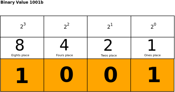
Reading from right to left:
- First position (rightmost) = 2⁰ = 1
- Second position = 2¹ = 2
- Third position = 2² = 4
- Fourth position = 2³ = 8
To convert binary to decimal, multiply each digit by its place value and add them up:
Example: 1001 in binary
- 1 × 8 = 8
- 0 × 4 = 0
- 0 × 2 = 0
- 1 × 1 = 1
- Total: 8 + 0 + 0 + 1 = 9 in decimal
Binary in Circuits
In your circuits, binary digits (called bits) are represented by voltage levels:
- 1 = high voltage (~5V)
- 0 = low voltage (~0V, ground)
This means we can use switches to create binary numbers! When a switch is ON, that bit is 1. When it's OFF, that bit is 0.
Note: Binary is a foundational concept in electrical engineering and computer science. Before moving on, make sure you understand this new number system and are completely comfortable converting back and forth from decimal. Check out the extra resources page for videos, exercises, and games on binary.
2) Representing Binary with DIP Switches
Remember our circuit from Prerequisite? We were using an 8-bit DIP switch to light up 8 LEDs, then we used the 8-bit DIP switch to light up different segments on the 7-segment display. We can use that same 8-bit DIP switch to represent an 8-digit binary number, where an OFF switch represents a 0 in that place value and an ON switch represents a 1!
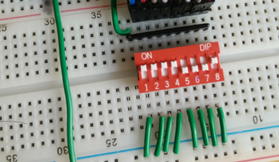
When reading a binary number off the DIP switch, ignore the numbers 1 through 8 on the bottom. Read it left to right, using the normal math convention that the rightmost digit is the ones place. It can be helpful to label your switches to match the binary place values diagram above.
You can practice setting numbers on your DIP switch with your circuit from Prerequisite. Note that your switches are still controlling arbitrary segments on your 7-segment display, so the number you are inputting will NOT match the shape displayed!
1. Set all switches to OFF. This represents 00000000 = 0.
2. Turn ON only the rightmost switch 8 (the ones position). This represents 00000001 = 1.
3. Turn ON only the switch labeled 7 (the twos position). This represents 00000010 = 2.
4. Turn ON switches 7 and 8. This represents 00000011 = 3.
Now we know one way to input a binary number to our circuit. Let's see how we can convert our DIP switch input into a decimal number to display.
3) Introduction to IC Chips
What is an IC?
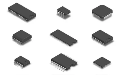
IC stands for Integrated Circuit. An IC chip is a small package containing dozens, thousands, or even millions of electronic components all working together to perform a specific function.
They come in all shapes and sizes, but the general idea is that you give it some inputs, it does some processing inside (which you don't need to understand yet), and it gives you outputs. Some of its metal legs (which we call pins) we use to send input, and some of its pins can send us output.
Each IC chip has a specific name, function, and pinout. The pinout diagram is how we know which pins are input and which output. Today we will use the 74LS48 IC, which converts a 4-bit binary number input into decimal output for a 7-segment display, and has the following pinout diagram:

Most ICs in this course come in a DIP (Dual In-line Package) format. This means:
- Two parallel rows of pins
- A notch or dot marks pin 1
- Pins are numbered counter-clockwise starting from pin 1
- The chip straddles the center gap of the breadboard
Important: Always place IC chips straddling the center gap so the two rows of pins don't accidentally connect to each other.
For the 74LS48:
- Pin 8: GND (ground)
- Pin 16: VCC (power, +5V)
- Pins 7, 1, 2, 6: Inputs (A, B, C, D) - these receive your 4-bit binary number
- Pins 9-15: Outputs (a, b, c, d, e, f, g) - these connect to the 7-segment display
Rule of thumb: Almost all DIP IC chips have power (VCC) on pin 16 and ground (GND) on pin 8. Always connect these first!
4) Wiring the 74LS48 IC
Now let's add the 74LS48 to your circuit and connect it to your binary input switches.
Step 1: Power the IC
1. Make sure your power is OFF.
2. Find your 74LS48 IC chip. The number should be written on the top black part of your IC. The end of the number sometimes has an E or N, which just describes how the chip is packaged for use. As long as the main letters and symbols line up, it's the same chip.
3. Place the IC on your breadboard straddling the center gap. Keep its orientation consistent with the pinout diagram above for easy wiring. Look for the notch or small dot that marks pin 1.
4. Using a jumper wire, connect the VCC IC pin to the power rail.
5. Using a jumper wire, connect the GND IC pin to the ground rail.
Step 2: Connect Inputs from the DIP Switch
Now we'll connect your DIP switch to the IC's input pins instead of directly to the 7-segment display. However, your DIP switch is 8 bits, and as we saw in the IC's pinout diagram, the 74LS48 only takes 4 inputs: A, B, C, and D. We will treat the DIP switch as a 4-bit input by only connecting its least significant (rightmost) four pins.
Looking at the IC pinout:
- Input A (LSB, least significant bit) = pin 7
- Input B = pin 1
- Input C = pin 2
- Input D (MSB, most significant bit) = pin 6
The inputs are in a strange order on the chip, so be careful!
6. Remove the jumper wires connecting your DIP switch to the 7-segment display.
7. Keep the DIP switch with one side of its pins connected to positive rail.
8. Connect the other pin of the rightmost switch (labeled 8) to the IC pin corresponding to the least significant bit.
9. Similarly connect switches 7, 6, and 5 to the IC pin corresponding to the correct place value.
Now check your circuit:
Why this order? The 74LS48 IC labels A as the least significant bit (LSB) and D as the most significant bit (MSB). We want switch 8 to control the 1's place, so it goes to input A.
Step 3: Connect Outputs to the 7-Segment Display
Remember the 7-segment display has 7 input pins that each control one LED segment. The 74LS48 IC both converts the 4-bit binary input into the decimal number to display and outputs the correct light-up pattern for the 7 segments on its 7 output pins. This is why we call this IC a BCD (Binary Coded Decimal)-to-7-segment decoder. We just need to connect the a-g output pins on the IC to the corresponding a-g input pins on the 7-segment display. Here is the pinout diagram again for reference.

10. Make sure the 7-segment display GND pins are still connected to the ground rail.
11. Connect the a-g IC output pins to the a-g 7-segment display input pins. Reading pinout diagrams is easier when your components are oriented in the same direction as the diagram.
Remember from the Prerequisite module that LEDs need a resistor in order to turn on. One option could be to connect each a-g pin of the IC to the corresponding a-g pin of the 7-segment LED with a resistor, but this would mean that every 7-segment display that we add requires 7 resistors. Instead, let's remember that it doesn't matter if the resistor comes before or after the LED, as long as they are next to each other in the circuit. With this in mind, we can instead put just one resistor between the GND pin of the 7-segment display and the GND rail. This way, regardless of which LED is on, the current will still pass through this resistor.
12. Connect a 220Ω resistor between the GND pin of the 7-segment display and the GND rail. All other resistors can be removed.
13. Connect the other GND pin(s) to the GND rail with black jumper wires.
This is a lot of wiring! Take your time and double-check each connection. It helps to do one segment at a time and test as you go.
A helpful technique: Use different colored wires for different segments to make debugging easier. For example:
- Red for segment a
- Orange for segment b
- Yellow for segment c
- And so on...
5) Testing Your Binary to Decimal Converter
Time for the moment of truth! Let's test your circuit.
13. Triple-check all connections. Mentally trace the flow of current from the power rail to the IC to the 7-segment display, and trace the flow of information by matching pins using each component's pinout diagram.
14. Turn power ON.
15. Set all DIP switches to OFF.
What do you see? The display should show "0"!
Now try different numbers:
16. Turn ON the rightmost switch. The display should show "1".
17. Turn OFF that switch and turn ON only the 7th switch. Display should show "2".
18. Turn ON both switches. Display should show "3".
19. Try making other numbers up to 15.
What About Numbers Above 9?
Try setting your switches to binary 1010 (decimal 10). What happens?
The 74LS48N can only display digits 0-9. When you input 10-15, you'll see strange patterns because these numbers don't exist in our normal base-10 system.
6) Debugging with a Multimeter
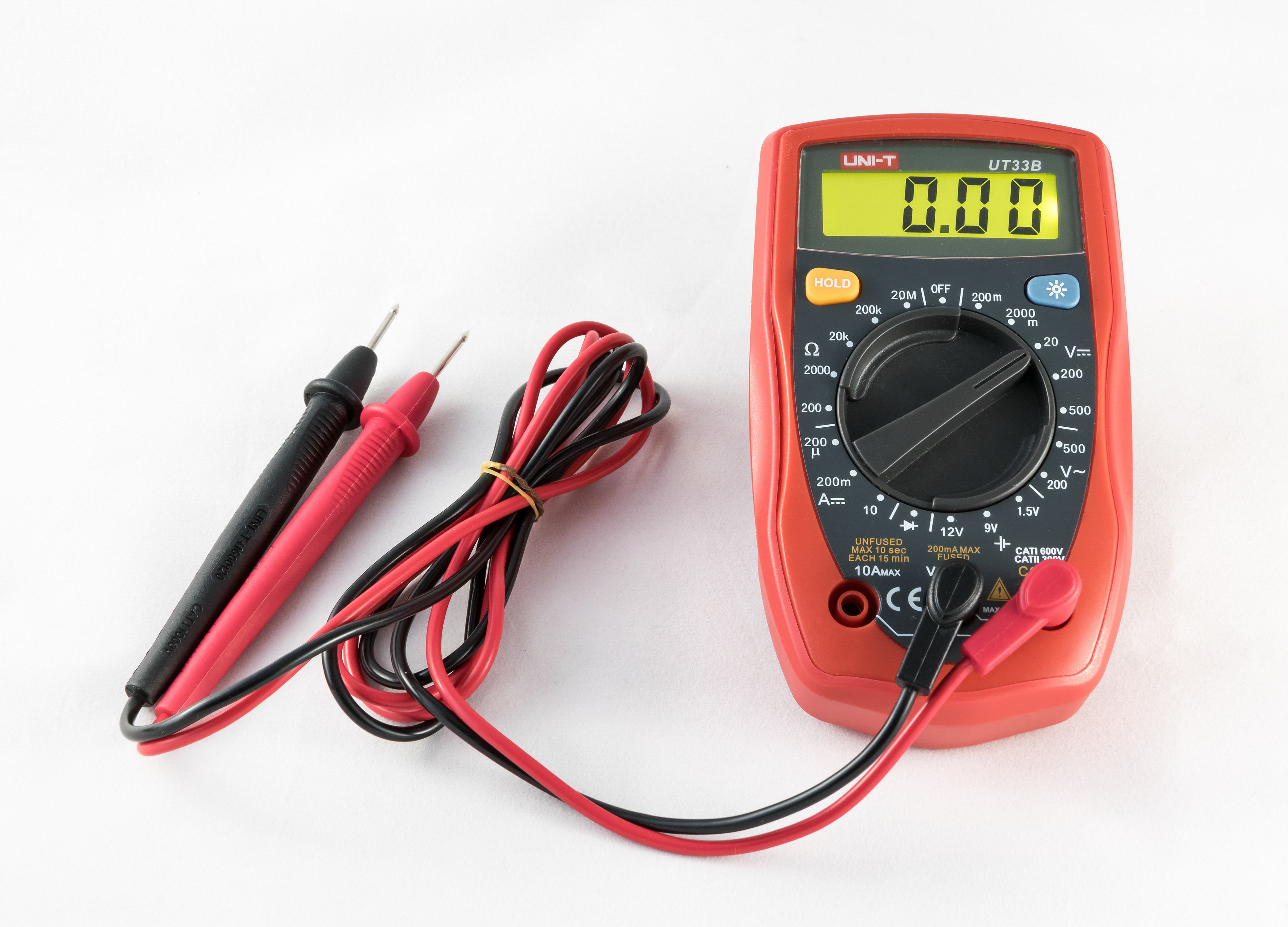
This is a multimeter, a tool used to measure electrical values in a circuit. In this course, you can use a multimeter to measure voltage, check how much current is flowing, or check the resistance of a component. Multimeters are your friends! They help you debug circuits by letting you test what is actually happening instead of guessing.
Let's verify the IC is receiving power correctly.
1. Set your multimeter to DC voltage mode (V⎓).
2. Turn your power ON.
3. Place the black probe on pin 8 (GND).
4. Place the red probe on pin 16 (VCC).
5. You should read approximately 5V. If not, check your power connections.
You can check if signals are reaching the IC:
1. Black probe on GND (IC pin 8)
2. Red probe on an input pin (like pin 7)
3. Turn corresponding switch ON - should read ~5V
4. Turn switch OFF - should read ~0V
If an input pin doesn't change voltage when you flip the switch, the wire isn't connected properly.
If your display is very dim, check your resistor values. Too much resistance results in a dim display; too little and you risk damaging the display.
7) Understanding What You Built
Let's review what just happened:
- You used DIP switches to create a 4-bit binary number
- Those switches send either 5V (binary 1) or 0V (binary 0) to the IC
- The 74LS48N chip reads those 4 bits
- Inside the chip, complex logic circuits decode the binary number
- The chip activates the correct output pins to light up segments
- The 7-segment display shows the decimal digit
This is exactly how computers work! They represent everything as binary (1s and 0s), process it with logic circuits, and convert it back to something humans can understand.
Why This Matters
You just built a fundamental building block of digital electronics. This same principle is used in:
- Digital clocks (coming in the next exercises!)
- Calculators
- Computer displays
- Instrument panels
- Any device that shows numbers
The only difference is they might have more bits (to show bigger numbers) or use different display technologies, but the core concept is the same.
8) Challenge: Verify the Truth Table
A truth table shows all possible inputs and their corresponding outputs. Let's create one for your circuit!
Try creating your own truth table:
| Binary Input (D C B A) | Decimal | Segments Lit |
|---|---|---|
| 0 0 0 0 | 0 | a,b,c,d,e,f |
| 0 0 0 1 | 1 | ? |
| 0 0 1 0 | 2 | ? |
...
Fill this in by testing each combination on your circuit!
9) Recap
Congratulations! You've learned:
✓ How binary numbers work and why computers use them
✓ What an IC chip is and how to read a pinout diagram
✓ How to properly power an IC (VCC and GND first!)
✓ How to connect inputs and outputs to an IC
✓ How to use a multimeter to verify voltages
✓ How to systematically debug a circuit
✓ How to build a binary-to-decimal decoder
Optional: Take It Further
Want to experiment more? Try these challenges:
-
Add a 5th LED that lights up only when your binary input is greater than 9 (hint: you'll need to use some of the strange patterns for 10-15)
-
Use your multimeter to measure the voltage on each output pin (13, 12, 11, 10, 9, 15, 14) for different inputs. When should each pin be HIGH (~5V) vs LOW (~0V)?
-
Can you figure out what segments light up for inputs 10-15? Draw the patterns you see.
Final Submission
In the next exercise, you'll learn about counters - ICs that automatically count in sequence. You'll combine what you learned here with a counter chip to build a circuit that counts from 0-9 automatically, without needing to flip switches manually.