4-bit Calculator
Congratulations! You have reached the final project of Module 4.
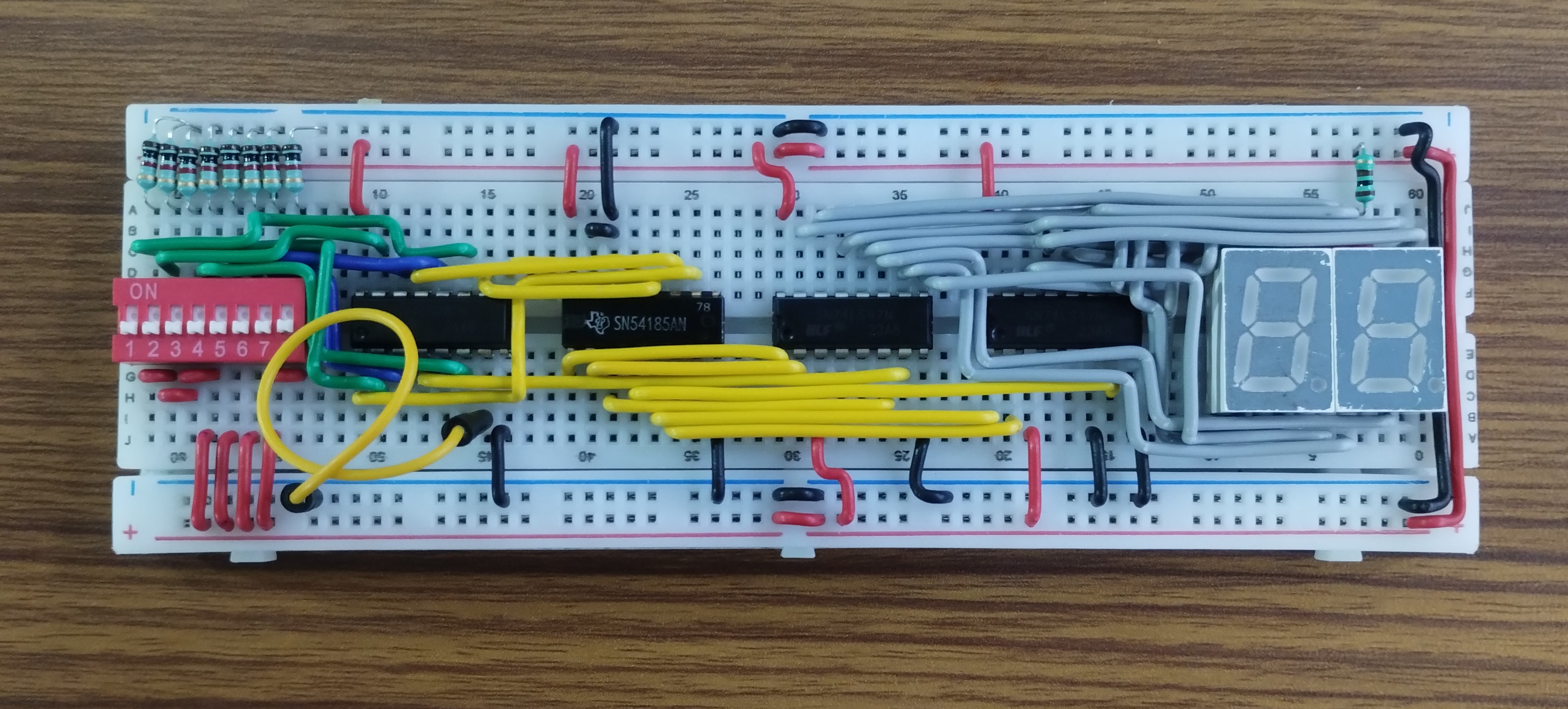
In previous exercises, you built an Adder (which speaks Binary) and a Decoder System (which speaks Human/Decimal). Now, you will combine these separate subsystems into a complete 4-Bit Calculator.
Project Objective: Build a circuit that accepts two 4-bit binary numbers via switches, adds them together, and displays the decimal result (0-30) on two 7-segment displays.
1) System Architecture
Our calculator works in three simple steps:
-
Add the Numbers (The Adder): We use the 74LS283 chip to add the binary numbers from your switches. It outputs the result in binary (like
11110for 30). -
Translate to Decimal (The Converter): We cannot read raw binary easily. The 74185 chip translates that binary result into two separate digits: a "Tens" digit and a "Ones" digit.
-
Show the Result (The Display): Finally, the 7447 chips take those digits and turn on the correct LEDs on the 7-segment displays so we can read the number (like "30").
2) Step-by-Step Build
Step 1: The Arithmetic Unit
First, we need to perform the math.
- Place the 74LS283 Adder on your breadboard.
- Connect Inputs A_1-A_4 and B_1-B_4 to your DIP switches.
- Important: Ground the Carry In (C_0) pin.
- Test: Connect temporary LEDs to the Sum outputs (S_1-S_4) and Carry Out (C_4). Verify that 1+1=2 (binary 0010). Once verified, remove the LEDs but keep the wires ready.

Step 2: The Translation Unit
Now we convert the Binary result (which can be up to 5 bits wide) into Decimal format.
- Place the 74185 Converter on the board.
- Connect the Sum outputs (S_1-S_4) from the Adder to the Binary Inputs (A-D) of the 74185.
- Connect the Carry Out (C_4) from the Adder to the next Binary Input (E) of the 74185.
- Ground the unused inputs (Enable, etc.) according to the datasheet.
- This chip will now output two sets of BCD data: one for the "Ones" place and one for the "Tens" place.
Step 3: The Display Unit
Finally, we show the result to the user.
- Place two 7447 Decoder chips.
- Connect the "Ones" BCD output from the 74185 to the first 7447.
- Connect the "Tens" BCD output from the 74185 to the second 7447.
- Wire the 7447 outputs (a-g) to your two 7-Segment Displays.
3) Final Testing
Power up your circuit! If all connections are correct, the displays should show "00".
Test Cases:
- Simple Addition: Set A=1, B=2. Display should read 03.
- Crossing 9: Set A=5, B=5. Display should read 10. (This proves the Tens digit logic works).
- Maximum Value: Set A=15 (all on), B=15 (all on). Display should read 30.
4) Final Project Submission
This is the big one! Show us your fully operational calculator.
In the next module, you will dive deeper in to binary arithmetics, and learn about advanced binary arithmetics including accumulation and binary subtraction!