Debounce
Welcome to Module 2! In Module 1, you built a cascading decade counter that counts from 0-99. You might have noticed that sometimes when you pressed the button once, the counter jumped by 2 or even 3 numbers. This wasn't a problem with your circuit – it's a real phenomenon called button bounce, and in this exercise, you'll learn how to fix it! By the end of this exercise, you'll understand why buttons bounce, how to visualize the problem, and how to solve it using a debounce circuit.
NOTE: Throughout this course, all the switches that serve as clock pulses must be debounced to avoid unwanted behaviour, especially in this module.
1) Understanding Button Bounce
What is Button Bounce?
When you press a mechanical button, you might think the connection happens instantly and cleanly. In reality, the metal contacts inside the button physically bounce against each other several times before settling into a stable connection.
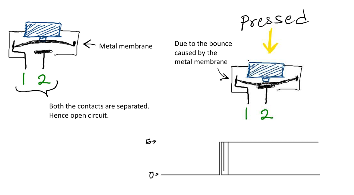
This bouncing happens incredibly fast – usually within 5-50 milliseconds – but it's fast enough that electronic circuits can detect each bounce as a separate button press. Think of it like dropping a basketball. When the ball hits the ground, it doesn't just stick – it bounces several times before settling. Similarly, when you press a button, the internal contacts bounce several times before making stable contact.

Why This Matters
For simple circuits like turning an LED on and off, button bounce doesn't matter – the LED just flickers for a few milliseconds, which you probably won't notice. But for counting circuits, each bounce is registered as a separate count. This is why your cascading decade counter from Module 1 sometimes skipped numbers!
2) Observing Button Bounce
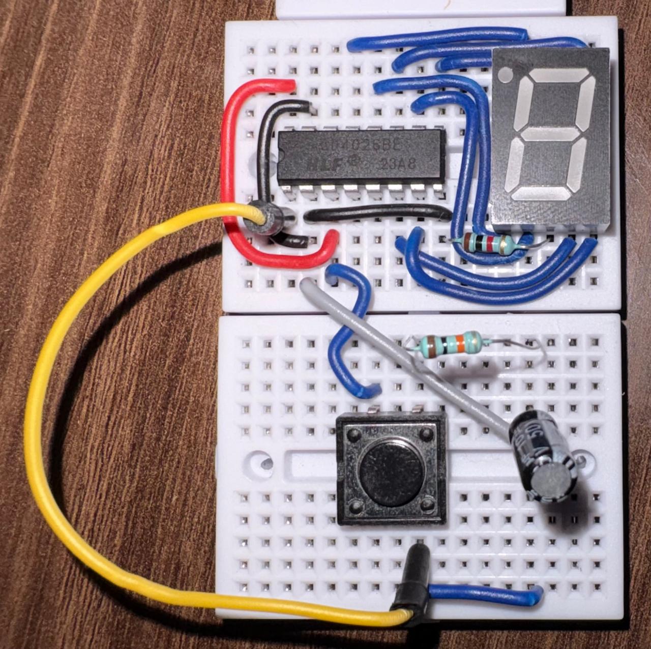
Let's see button bounce in action using the CD4026 cascading decade counter you built in the previous module.
Spurious Increments Test
- Ensure your CD4026 counter circuit is powered ON and currently displays a number.
- Connect a basic tactile button directly to the clock input (Pin 1) of your first CD4026, with a pull-down or pull-up resistor (whichever way you originally wired your manual trigger).
- Press the button carefully and repeatedly.
- Observe the 7-segment display closely as you actuate the switch.
You should notice that occasionally, a single press causes the counter to jump by 2, 3, or even more numbers! This unpredictable behavior is the direct result of the button contacts physically bouncing.
3) Building a Debounce Circuit
To fix button bounce, we need to "smooth out" the bouncing signal so that multiple bounces are treated as a single button press. We do this with an RC circuit – a combination of a Resistor and a Capacitor.
Now let's build a proper debounce circuit for your button. You'll need:
- 1 × 10kΩ resistor
- 1 × 10µF capacitor
Electrolytic Capacitors and Polarity
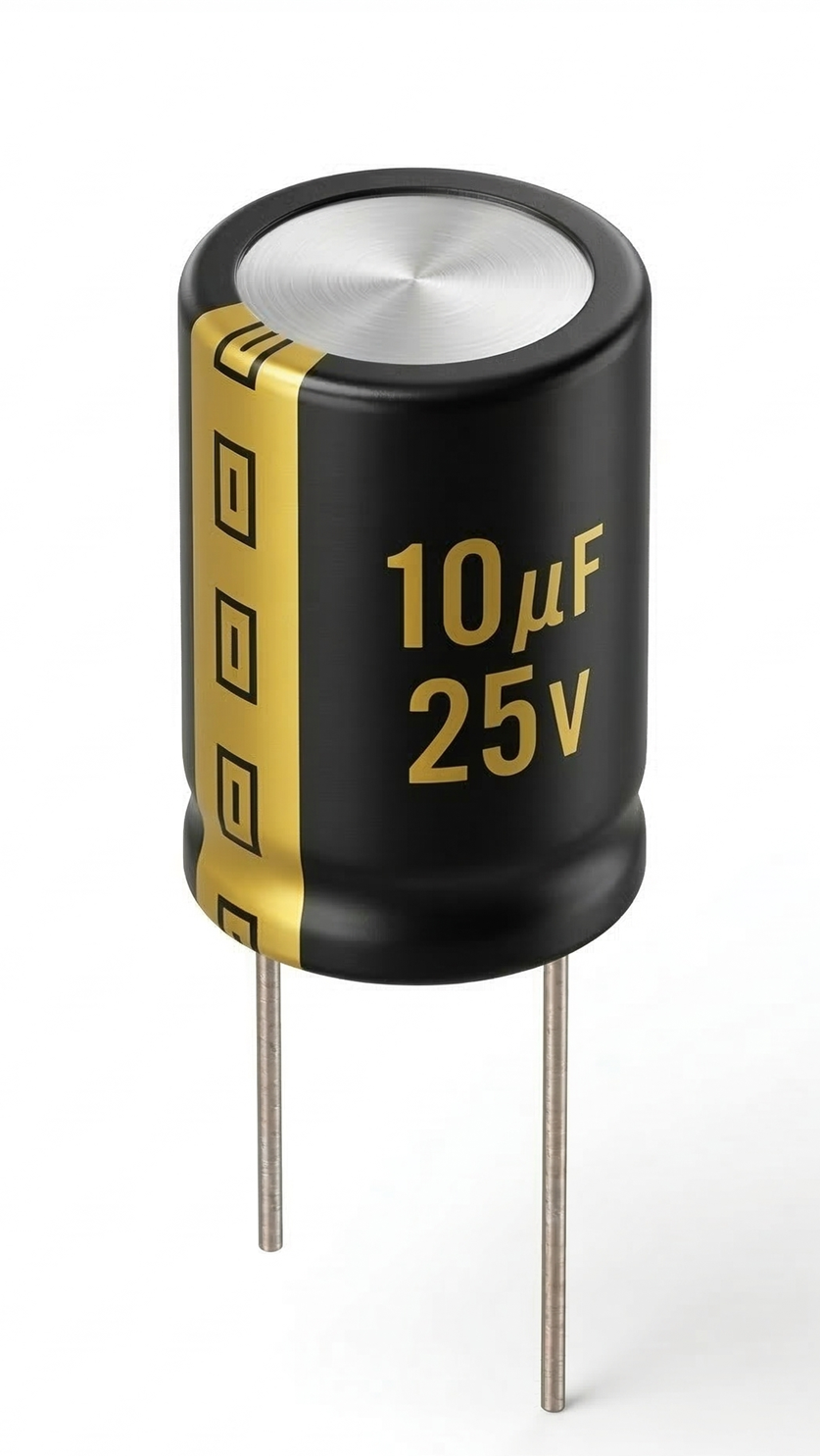
The 10µF capacitor you'll use is an electrolytic capacitor. Unlike resistors, these capacitors have polarity – they must be connected in the correct direction or they can be damaged. Electrolytic capacitors have two legs:
- Positive leg (anode): Usually longer, connected to higher voltage
- Negative leg (cathode): Shorter, has a stripe with minus signs (-) on that side of the cylinder, connected to lower voltage (usually GND)
The Circuit
1. Turn your power OFF.
2. Connect your button so it spans the middle gap of the breadboard.
3. Connect one leg of the button directly to GND.
4. On the other side of the button (the leg that connects when pressed):
a. Connect a 10kΩ resistor from this pin to 5V (pull-up resistor)
b. Connect the positive leg (longer) of your 10µF capacitor to this pin
c. Connect the negative leg (shorter, marked with -) of the capacitor to GND
5. Connect a wire from this same pin (where the resistor, capacitor, and button meet) to the clock input (Pin 1) of your CD4026.
Why This Works
Pull-up Resistor (10kΩ to 5V):
- When the button is NOT pressed, this resistor "pulls" the voltage up to 5V (HIGH)
- This ensures the signal is always in a known state (not "floating")
Capacitor (10µF):
- Smooths out voltage changes caused by button bounce
- Creates a gradual voltage rise instead of instant jumps
Button to GND:
- When pressed, connects the circuit to ground
- When released, the pull-up resistor brings voltage back to HIGH
6. Turn your power ON.
7. Test your debounced button! Press it rapidly – the counter should reliably increment by exactly 1 every time.
4) Debouncing Your Cascading Counter
Now that you understand debouncing, let's apply it to your full cascading decade counter from Module 1!
Your counter has multiple buttons:
- One button for incrementing the count
- One button for reset
Let's debounce both of them.
Debouncing the Increment and Reset Buttons
1. Turn your power OFF.
2. Build the debounce circuit (10kΩ pull-up, 10µF capacitor, button to GND) for your increment button.
3. Connect the output to the clock pin (Pin 1) of the FIRST CD4026.
4. Build a SECOND identical debounce circuit for your reset button.
5. Connect the output of this second circuit to the reset pins (Pin 15) of BOTH CD4026 ICs.
6. Turn your power ON and test both buttons.
Why Do We Need the Resistor?
You might wonder – why not just connect the button directly between 5V and the clock pin?
The pull-up resistor serves two important purposes:
1. Prevents floating inputs: When the button is not pressed, without a pull-up resistor, the clock pin would be floating – not connected to anything. Floating inputs can randomly pick up electrical noise and trigger the circuit unexpectedly.
2. Limits current: When you press the button, if one side were directly connected to 5V, pressing it would create a short circuit from 5V to GND. The resistor limits the current flow, protecting your power supply.
5) Reading Circuit Diagrams
So far, we've used written steps and photos to describe circuits. As circuits get more complex, this becomes confusing. Engineers use circuit diagrams (or schematics) to show how components connect.
Here is the circuit diagram for the debounce circuit you just built:
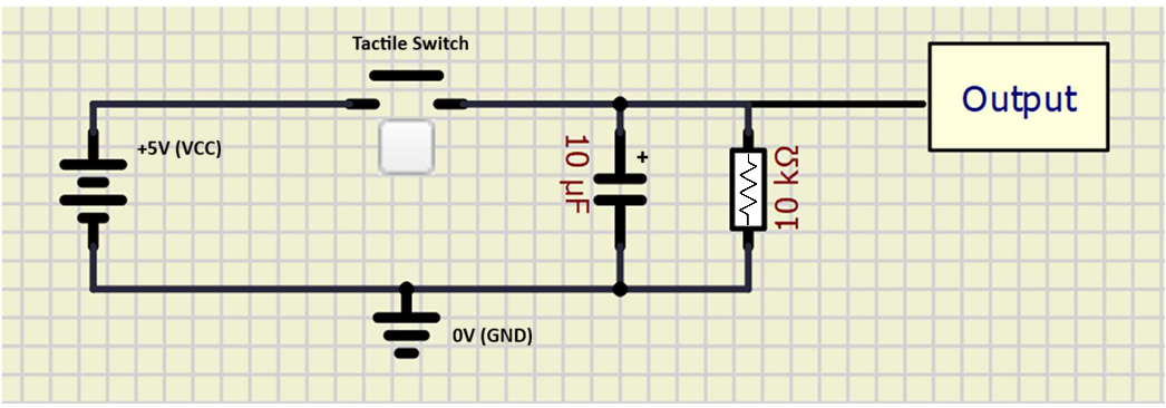
Let's break down the symbols:
| Symbol Image | Name | What it means |
|---|---|---|
 |
Resistor | The zig-zag line represents resistance to current flow |
 |
Capacitor | Two parallel lines (sometimes one curved) represent the two plates of a capacitor |
 |
Switch/Button | A line with a break that can be closed to make a connection |
 |
Ground (GND) | 0V reference point. All ground symbols connect together |
 |
5V/VCC | Positive power supply |
Reading schematics is a crucial skill in electronics. Instead of showing the physical layout (where things go on the breadboard), schematics show the logical connections between components.
6) Recap
Congratulations! You've learned:
✓ Why mechanical buttons bounce and how it affects counting circuits
✓ How to observe button bounce using your cascading counter
✓ How to build a debounce circuit with a pull-up resistor and capacitor
✓ How to read basic circuit diagrams
✓ How to apply debouncing to multiple buttons
Your cascading counter should now work perfectly, incrementing by exactly 1 with each button press!
Final Submission
In the next exercise, you'll begin with the fundamentals of sequential logic - Latches!