Double Dabble
Please Log In for full access to the web site.
Note that this link will take you to an external site (https://accounts.google.com) to authenticate, and then you will be redirected back to this page.
In the previous exercise, we built circuits that calculate in Binary.
- Binary:
1111 - Human Readable:
15
To display binary values (like on a 7-segment display), we need conversion. The algorithm we use for this is called Double Dabble (or Shift-Add-3).
1) The Double Dabble Algorithm
How it Works
We take our binary number and shift it into "bins" representing our decimal digits (Ones, Tens, Hundreds). However, a 4-bit binary digit can go up to 15, but a decimal digit can only go up to 9.
- The Rule: If any 4-bit BCD column is 5 or greater, we must add 3 to it before the next shift.
Why Add 3? When converting binary to decimal, we need to ensure that each 4-bit group (BCD digit) stays valid (0-9). If a group becomes \ge 5, we add 3. This correction prevents invalid BCD digits (like 1010=10).
Example: Converting 15 (1111)
Let's trace the conversion of the binary number 1111.
| Operation | Tens Column | Ones Column | Remaining Binary | Note |
|---|---|---|---|---|
| Start | 0000 | 0000 | 1111 | Initial State |
| Shift 1 | 0000 | 0001 | 111 | |
| Shift 2 | 0000 | 0011 | 11 | Value is 3 (<5), keep going. |
| Shift 3 | 0000 | 0111 | 1 | Value is 7 (\ge5)! ADD 3. |
| Add 3 | 0000 | 1010 | 1 | 7 + 3 = 10 (1010) |
| Shift 4 | 0001 | 0101 | - | The '1' from Ones shifts to Tens. |
| Result | 1 | 5 | 15 |

2) Implementing the Double Dabble Algorithm
The 74185 Binary-to-BCD Converter
This is an example of an IC which implements the logic of this algorithm. We will be using it as a reference for the intended behaviour.
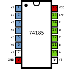
- Function: Converts 6-bit Binary input into 6-bit BCD output.
- Cascading: You can connect multiple 74185 chips together to convert larger numbers (8-bit, 16-bit, etc.).
- Usage: Simply connect your binary source (switches or adder output) to the Binary Inputs and take the BCD Outputs to the next stage.
- Note: In the inputs,
Ais the least significant bit andEis the most significant bit, and for the output,Y1is least significant andY6is most significant. 74185 does not use pinsY7andY8, and those are internally unconnected
Refer to this to see how to connect the inputs and outputs. Note that the datasheet is for two different ICs, 74184 and 74185, and that the input/output diagrams for 74185 are on pages 7 and 8.
Use this link if the file does not open below:
Refer to Figs. 4 and 5 above for up to 8 bits of input. Note that the least significant input bit always goes directly to the output, bypassing the IC.
An example implementation
Inputs: B_0,B_1,B_2,B_3,B_4,B_5
Outputs: Y_0,Y_1,Y_2,Y_3,Y_4,Y_5,Y_6
Detector (Comparator and AND): This checks at the 4-bit digit and outputs “HIGH” if the digit is 5 or more. A digit in binary is 5 or more if its 8’s bit is HIGH, or if the 4's bit is HIGH along with either the 2's bit or the 1's bit being HIGH
\big[A \ge 5\big]\equiv \big[A_8 OR (A_4 AND (A_2 OR A_1))\big]
Adder: The detector’s yes/no signal is wired into the two least significant bits of the adder’s second input (input B), so the adder adds a correction of 3 when the digit is 5 or more, and 0 otherwise.
This is cascaded three times to give the conversion from 6 binary bits to 2 BCD digits (going from 00 to 63).
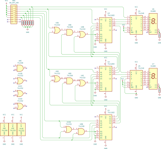
3) Building the double-dabble circuit
Components needed
- 1× 8-bit DIP switch
- 2× 7-segment common cathode LED
- 3× 74283 (4-bit adder) IC
- 2× 7448 (BCD to 7-segment converter) IC
- 1× 7408 (AND gates) IC
- 2× 7432 (OR gates) IC
- 8× 220Ω resistors
Schematic
Final Submission
In this module's project, you'll make a simple 4-bit calculator that can add two binary numbers.