Digital Clock
Now it's time to put everything together and build a real working digital clock that displays hours:minutes:seconds!
This is your most complex project yet. Take your time, test each section as you build it, and don't hesitate to refer back to the exercises and the Resources page when you need help.
1) Project Overview
In this project, you'll build a compact digital clock that:
- Displays time in HH:MM:SS format (hours:minutes:seconds)
- Uses six 7-segment displays (2 for hours, 2 for minutes, 2 for seconds)
- Counts seconds automatically using a 555 timer or crystal oscillator
- Resets seconds and minutes at 60
- Resets hours at 12
- Has buttons to set the time manually
Parts You'll Need:
ICs:
- 6 × CD4026 decade counter ICs (one for each digit)
- 1 × 555 Timer IC (for clock pulse generation)
- 1 × 74LS00 NAND gate IC (for hour reset at 12)
Displays:
- 6 × Common cathode 7-segment displays
Resistors:
- 6 × 220Ω resistors (for display current limiting)
- 3 × 10kΩ resistors (pull-up resistors for buttons)
- 1 × 10kΩ resistor (for 555 timer)
Capacitors:
- 3 × 10µF electrolytic capacitors (for button debouncing)
- 1 × 10µF electrolytic capacitor (for 555 timer)
- 1 × 0.01µF capacitor (marked 103, for 555 timer)
Diodes:
- 6 × 1N4148 diodes (for reset circuits)
Variable Components:
- 1 × 1MΩ potentiometer (for adjustable 555 timer frequency)
Switches:
- 3 × Push buttons (for time setting and reset)
Power:
- 1 × 5V power supply with breadboard adapter
Breadboards and Wire:
- 6 × Small breadboards (170 pin) OR 2 × Large breadboards
- Jumper wires in various colors
Optional but Recommended:
- LED for testing clock pulse
- Multimeter for debugging
2) Project Strategy
This is a big project! Don't try to build everything at once. Instead, follow this strategy:
1. Build in sections:
- Start with seconds (2 digits)
- Add minutes (2 digits)
- Add hours (2 digits)
- Test each section before moving to the next
2. Test as you go:
- Use a faster clock signal (10 Hz) for testing
- Verify each digit counts correctly
- Check reset circuits before cascading
- Slow down to 1 Hz for final operation
3. Keep it organized:
- Use different colored wires for different signals
- Label your breadboards (seconds, minutes, hours)
- Keep power and ground rails consistent
- Document connections as you build
4. Debug systematically:
- Test power to each IC first (VCC and GND)
- Verify clock signals reach each counter
- Check reset circuits one digit at a time
- Use your multimeter to trace signals
3) Building the Seconds Counter
Let's start by building the seconds section: two digits that count from 00 to 59, then reset.
Step 1: Set Up Two Counter ICs
1. With power OFF, place two CD4026 ICs on small breadboards (or on one section of a large breadboard), one for units digit and one for tens digit.
2. Leave two rows at the top and bottom of each breadboard for power rails.
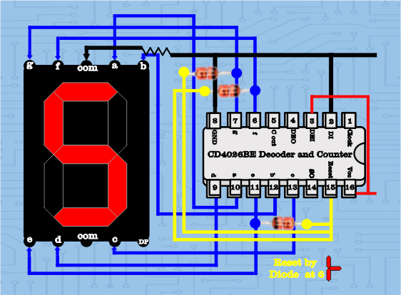
3. For each CD4026:
- Connect pin 8 (GND) → ground rail
- Connect pin 16 (VCC) → power rail
- Connect pin 2 (Clock Inhibit) → GND
- Connect pin 3 (Display Enable In) → VCC
Remember: Always connect power (pins 8 and 16) to each IC before anything else!
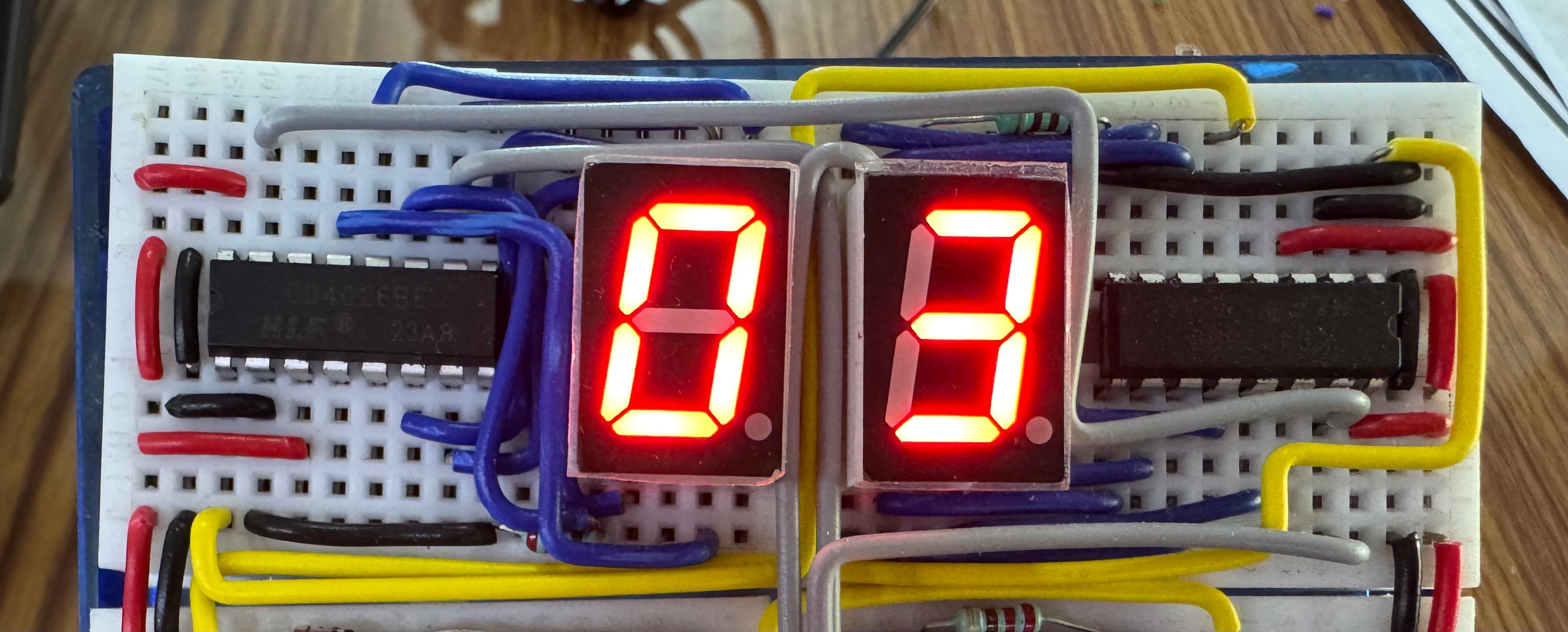
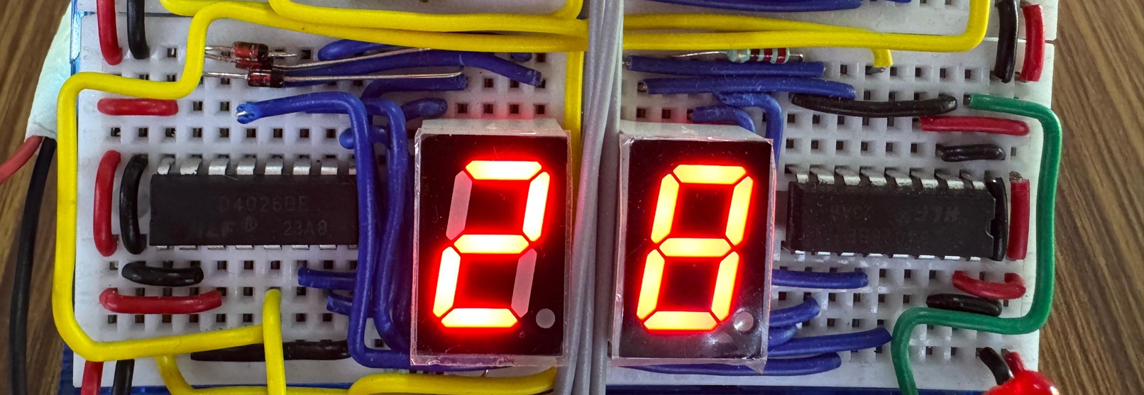
Step 2: Connect the 7-Segment Displays
4. Place two 7-segment displays next to their respective CD4026 ICs.
5. For each display:
   - Connect segments a through g from the CD4026 output pins to the corresponding display pins
   - Connect the common cathode pin(s) to GND through a 220Ω resistor
Tip: Use different colored wires for each segment to make troubleshooting easier:
- Segment a: Red
- Segment b: Orange
- Segment c: Yellow
- Segment d: Green
- Segment e: Blue
- Segment f: Purple
- Segment g: White/Gray
6. Turn power ON briefly. Both displays should show "0". If not, check:
   - Power connections to both ICs
   - Display enable (pin 3) connected to VCC
   - Segment connections between IC and display
   - Common cathode resistor and ground connection
Step 3: Cascade the Counters
7. With power OFF, connect the carry signal:
   - Pin 5 (Carry Out) of units digit CD4026 → Pin 1 (Clock) of tens digit CD4026
This makes the tens digit increment every time the units digit rolls over from 9 to 0.
Step 4: Add Reset at 60
Now we implement the clever diode reset circuit you learned in Exercise 3!
8. For the TENS digit CD4026 only:
   - Remove any direct connection from pin 15 (Reset) to GND
   - Connect three 1N4148 diodes in parallel:
     • All cathodes (black band) connect together to pin 15 (Reset)
     • First diode anode → pin 14 (segment e output)
     • Second diode anode → pin 10 (segment f output)
     • Third diode anode → pin 15 (segment g output)
   - Connect a 10kΩ resistor from pin 15 (Reset) to GND
9. Connect the tens digit reset pin (pin 15) to the units digit reset pin (pin 15)
   - This makes both digits reset simultaneously
How this works:
- When tens digit displays 0-5: At least one of segments e, f, g is OFF → reset pin stays LOW
- When tens digit reaches 6: All three segments e, f, g are HIGH → diodes block current → reset pin goes HIGH → both digits reset to 00
10. Test the reset circuit:
    - Connect a temporary button between VCC and pin 1 (Clock) of the units digit
    - Press rapidly to count up: 00, 01, 02... 58, 59
    - On the next press, it should reset to 00 instead of showing 60
If reset doesn't work:
- Check diode orientations (cathodes must face reset pin)
- Verify all three diodes connect to the correct segment pins
- Make sure 10kΩ pull-down resistor is connected
- Test with multimeter: segments e, f, g should all be ~5V when displaying 6

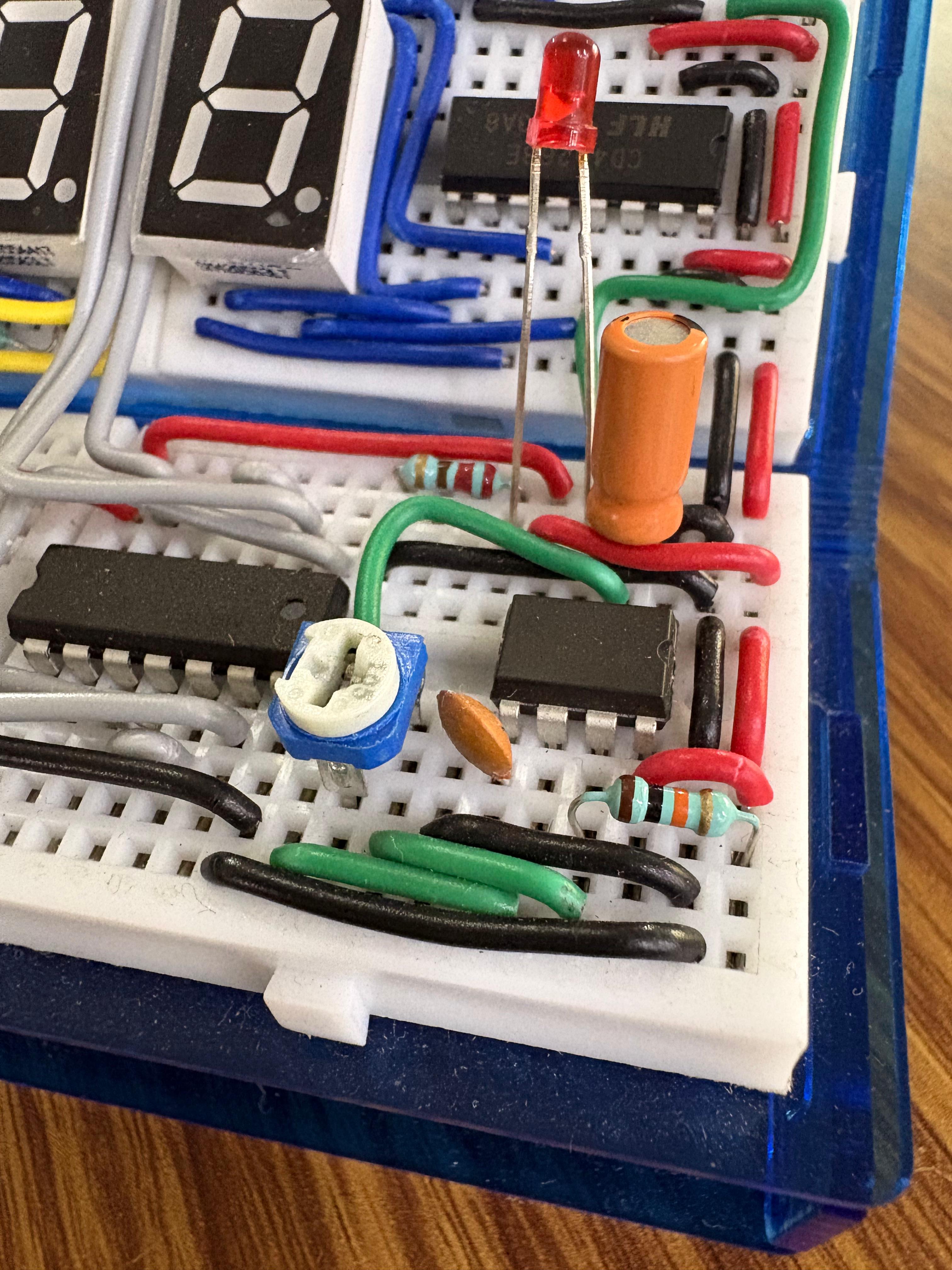
4) Building the Clock Pulse Generator
Your seconds counter needs a clock signal to tick automatically. You'll build a 555 timer circuit that generates pulses at approximately 1 Hz (once per second).
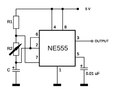
555 Timer Clock Circuit
1. On a separate breadboard area, place the 555 timer IC straddling the center gap.
2. Connect power first:
   - Pin 1 (GND) → ground rail
   - Pin 8 (VCC) → power rail
3. Connect timing components:
   - Pin 7 (Discharge) to one end of a 10kΩ resistor
   - Other end of 10kΩ resistor to VCC
   - Pin 7 also connects to one outer pin of the 1MΩ potentiometer
   - Middle pin (wiper) of potentiometer to pins 2 and 6 (connect these together)
   - Pins 2 and 6 also connect to positive leg of 10µF capacitor
   - Negative leg of 10µF capacitor to GND
4. Connect control pins:
   - Pin 4 (Reset) → VCC (keeps timer enabled)
   - Pin 5 (Control Voltage) → 0.01µF capacitor → GND
5. Connect output:
   - Pin 3 (Output) → pin 1 (Clock) of seconds units digit CD4026
6. Turn power ON. Your seconds counter should start incrementing automatically!
7. Adjust the potentiometer to get approximately 1 second per count.
   - Turn clockwise for slower
   - Turn counter-clockwise for faster
Testing tip: For initial testing, set the 555 to count much faster (5-10 Hz). This lets you verify the reset at 60 happens correctly without waiting a full minute. Once everything works, slow it down to 1 Hz.
Optional: Add a visual indicator
- Connect an LED with 220Ω resistor from pin 3 to GND
- The LED will blink with each clock pulse
- Helps verify timing without watching the display
5) Building the Minutes Counter
The minutes section is almost identical to seconds – two digits counting 00-59 with the same reset circuit.
Minutes Assembly
1. On separate breadboard space, build another two-digit counter just like you did for seconds:
   - Two CD4026 ICs (units and tens)
   - Two 7-segment displays
   - Connect segments a-g from each IC to its display
   - Connect power, clock inhibit, and display enable for each IC
2. Connect the carry signal:
   - Units digit pin 5 (Carry Out) → tens digit pin 1 (Clock)
3. Add the diode reset circuit on tens digit:
   - Three 1N4148 diodes from segments e, f, g to reset pin
   - 10kΩ resistor from reset pin to GND
   - Connect both reset pins together
Cascade from Seconds to Minutes
The minutes should only increment when seconds rolls over from 59 to 00.
4. Connect the cascade:
   - Seconds tens digit pin 5 (Carry Out) → minutes units digit pin 1 (Clock)
How this works:
- Seconds units carries to seconds tens at 9→0
- Seconds tens carries to minutes units at 59→00
- Minutes units carries to minutes tens at 9→0 (for 10, 20, 30... minutes)
- Minutes tens has diode reset at 6 (giving 00-59 range)
5. Test the cascading:
   - Set your 555 timer to fast mode (5-10 Hz)
   - Watch as seconds counts to 59, resets to 00
   - Minutes should increment by 1 each time seconds resets
   - Let it run until minutes reaches 59
   - On the next rollover, minutes should reset to 00
If minutes don't increment:
- Check the carry connection from seconds tens to minutes units
- Verify minutes units clock pin (pin 1) receives pulses
- Use multimeter to check: seconds tens pin 5 should pulse HIGH briefly at 59→00
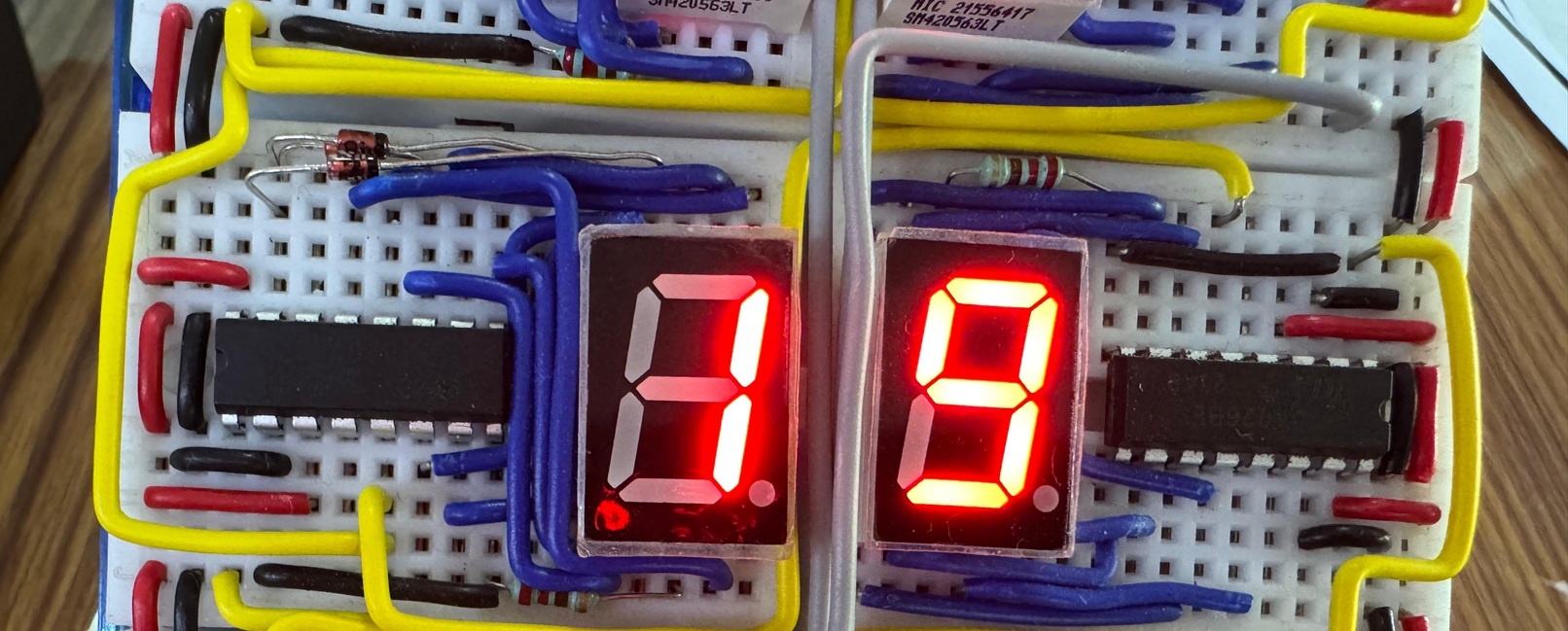
6) Building the Hours Counter
The hours section is different – it needs to count from 00 to 11 (or 01 to 12), then reset. This requires a different reset approach using logic gates.
Hours Assembly
1. Build another two-digit counter for hours:
   - Two CD4026 ICs (units and tens)
   - Two 7-segment displays
   - Connect segments, power, and control pins as before
2. Connect the carry signal:
   - Units digit pin 5 (Carry Out) → tens digit pin 1 (Clock)
3. Cascade from minutes:
   - Minutes tens digit pin 5 (Carry Out) → hours units digit pin 1 (Clock)
Now for the tricky part: resetting at 12.
Reset at 12 Using Logic Gates
We need to detect when the display shows "12" and trigger a reset. According to the reference document, we'll use the 74LS00 NAND gate IC.
The strategy:
- Detect when tens digit shows "1" (segment b HIGH)
- Detect when units digit shows "2" (segments a and g HIGH)
- Combine these conditions with NAND gates
- Output HIGH to reset pins when "12" is detected
4. Place the 74LS00 NAND gate IC on your breadboard.
5. Connect power:
   - Pin 14 (VCC) → 5V
   - Pin 7 (GND) → GND
Implementing the detection logic:
Looking at the reference circuit diagram from the project PDF:
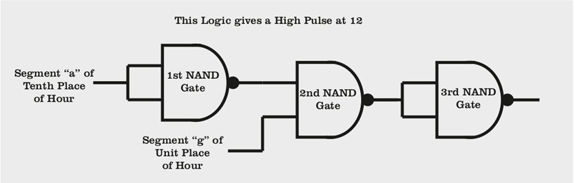
6. Connect the first NAND gate (pins 1, 2, 3):
   - Pin 1 → segment "a" output from tens place (pin 9 of tens digit IC)
   - Pin 2 → segment "a" output from tens place (same as pin 1)
   - Pin 3 is the output of this gate
Wait – why connect both inputs to the same segment? This effectively creates an inverter (NOT gate) because NAND(A,A) = NOT(A).
Actually, looking more carefully at the project PDF's approach, the exact logic is:
- Use segment outputs that are uniquely HIGH at "12"
- The circuit uses three cascaded NAND gates
- First NAND checks tens digit "a" (HIGH at 1)
- Second NAND checks units digit "g" (HIGH at 2)
- Third NAND combines them
Simplified approach for this project:
Since the exact logic circuit in the PDF is complex, here's a practical implementation:
6. Connect detection logic:
   - Wire segment "a" from tens digit (only HIGH when tens=1)
   - Wire segment "g" from units digit (HIGH when units=2)
   - Use NAND gates to detect both conditions
   - Output goes HIGH only when display shows "1" and "2"
7. Connect the reset:
   - NAND output → both hours digits reset pins (pin 15)
   - Add 10kΩ resistor from each reset pin to GND
8. Test the hours reset:
   - Use a button to manually clock the hours units digit
   - Count: 00, 01, 02... 10, 11
   - On the next increment, it should reset to 00 (not display 12)
Alternative for 1-12 display (instead of 0-11):
Some clocks display 1-12 instead of 0-11. To achieve this:
- Let the clock count normally to 12
- Reset to 01 instead of 00
- This requires initializing hours to 01 on startup or after reset
This is more complex and optional for this project.
7) Adding Time-Setting Buttons
Your clock needs buttons to set the time manually. You'll add three buttons with debouncing:
- Set Hours: Increments hours
- Set Minutes: Increments minutes
- Reset/Set Seconds: Sets seconds to 00
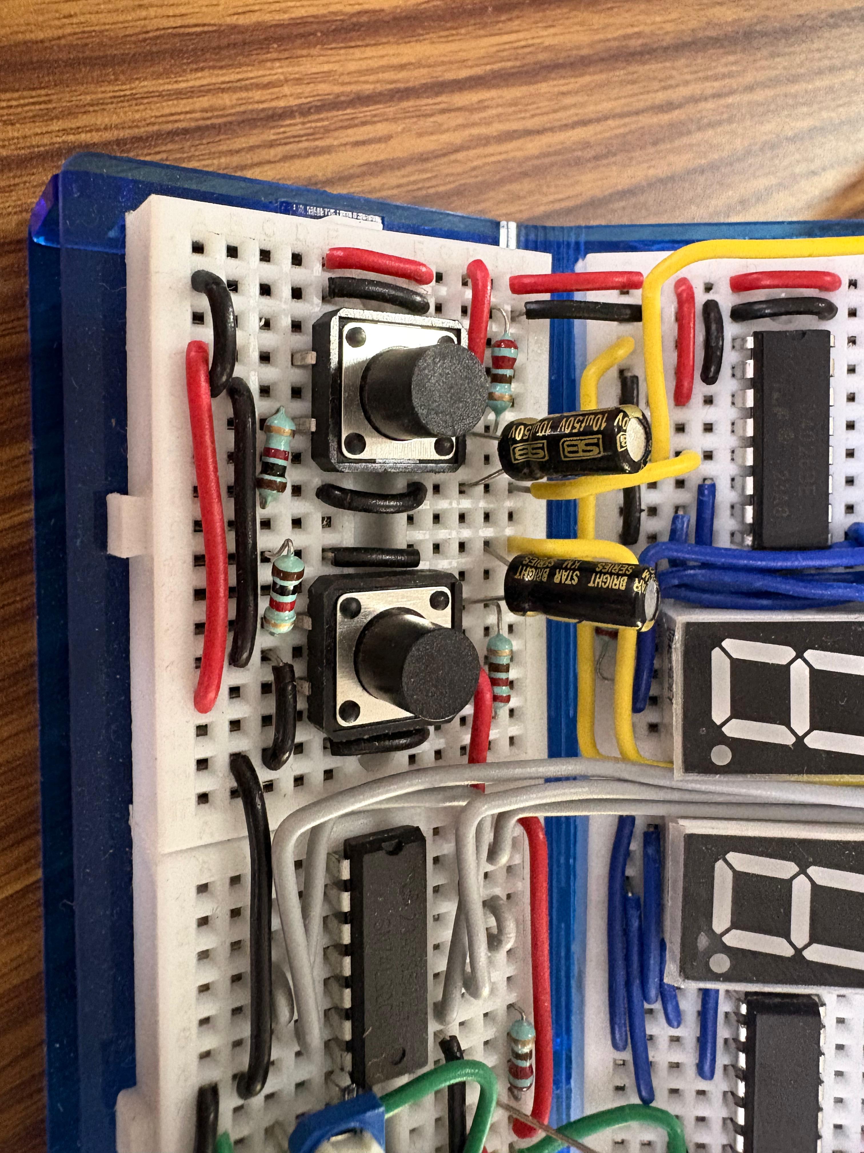
Building Debounced Buttons
For each button, you'll need:
- 1 × Push button
- 1 × 10kΩ resistor (pull-up)
- 1 × 10µF capacitor (debounce)
1. Build the hours set button:
   - One side of button → GND
   - Other side of button → hours units digit pin 1 (Clock)
   - 10kΩ resistor from clock pin → VCC (pull-up)
   - 10µF capacitor positive leg → clock pin
   - 10µF capacitor negative leg → GND
2. Build the minutes set button:
   - Same circuit as hours button
   - Connect to minutes units digit pin 1 (Clock)
3. Build the seconds reset button:
   - One side of button → VCC
   - Other side → seconds units digit pin 15 (Reset)
   - Also connect to seconds tens digit pin 15 (Reset)
   - 10kΩ resistor from reset pins → GND (pull-down)
   - 10µF capacitor positive leg → button output
   - 10µF capacitor negative leg → GND
Note: The seconds reset button is different – it goes to the reset pins, not the clock pin. This lets you quickly set seconds to 00.
4. Test the buttons:
   - Press "Set Hours" – hours should increment by 1
   - Press "Set Minutes" – minutes should increment by 1
   - Press "Reset Seconds" – seconds should jump to 00
If buttons don't work or increment multiple times:
- Check capacitor polarity
- Verify pull-up/pull-down resistor connections
- Make sure button is oriented correctly (check continuity)
- Try pressing more slowly and firmly
8) Final Assembly and Wiring
Now you need to connect everything together with proper power distribution.
Power Distribution
All six CD4026 ICs, the 555 timer, and the 74LS00 need power. Make sure your power supply can handle the current (should be fine with a standard 5V 1A supply).
1. Connect all breadboard power rails together:
   - Use red jumpers to connect all VCC rails
   - Use black jumpers to connect all GND rails
2. Connect the main power adapter:
   - Red wire → any VCC rail
   - Black wire → any GND rail
3. Verify power at each IC:
   - Use multimeter to check voltage at each IC's pin 8 (GND) and pin 16 (VCC)
   - Should read approximately 5V between them
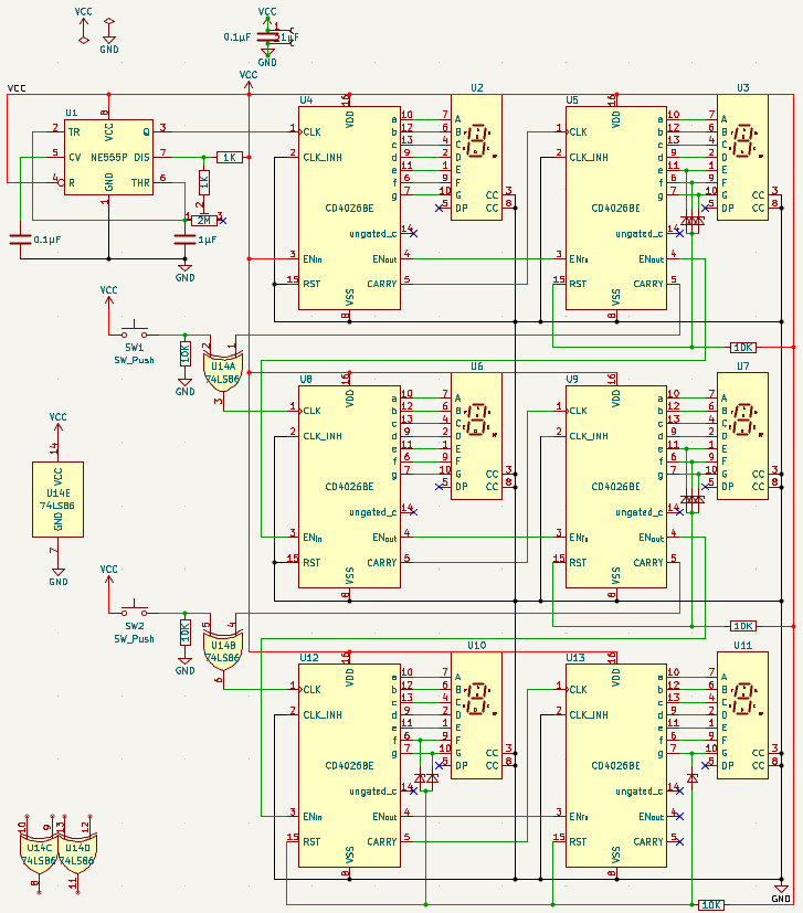
Signal Flow Summary
Let's trace the signal flow through your complete clock:
Clock generation: 555 Timer → 1 Hz pulse → Seconds units digit
Seconds counting: Seconds units (0-9) → carry → Seconds tens (0-5) → diode reset at 6
Minutes counting: Seconds tens carry → Minutes units (0-9) → carry → Minutes tens (0-5) → diode reset at 6
Hours counting: Minutes tens carry → Hours units (0-9) → carry → Hours tens (0-1) → logic gate reset at 12
Time setting: Buttons → debounce circuits → clock/reset pins
9) Testing and Calibration
Your clock is assembled! Now let's test and calibrate it.
Initial Testing
1. With power OFF, triple-check all connections:
   - Power to every IC
   - Segments from ICs to displays
   - Carry signals between digits
   - Reset circuits on tens digits
   - Button connections
2. Turn power ON
3. All displays should show "0" (or "00:00:00")
4. Within 1 second, seconds should start incrementing
Testing the Full Cycle
5. Speed up the 555 timer (turn potentiometer to ~5 Hz)
6. Watch the clock count rapidly:
   - Seconds: 00 → 59 → 00 (resets properly)
   - Minutes: Increments each time seconds resets
   - Minutes: 00 → 59 → 00 (resets properly)
   - Hours: Increments each time minutes resets
   - Hours: 00 → 11 → 00 (resets properly at 12)
7. Test set buttons:
   - Hours button increments hours
   - Minutes button increments minutes
   - Seconds reset button sets seconds to 00
If any section doesn't reset:
- Check diode orientations and connections
- Verify reset pin connections
- Test with multimeter: measure reset pin voltage at reset value
- Review the specific reset circuit (diodes for 60, logic gates for 12)
Calibrating to Real Time
8. Adjust the 555 timer for exactly 1 Hz:
   - Use a stopwatch or phone timer
   - Start timing when seconds shows 00
   - After 60 real seconds, check if display also shows 00
   - If display is ahead: Turn potentiometer clockwise (slower)
   - If display is behind: Turn potentiometer counter-clockwise (faster)
   - Repeat until synchronized
9. For better accuracy, time over several minutes:
   - Let clock run for 10 minutes
   - Calculate error: (clock time - real time) / real time
   - Adjust potentiometer accordingly
Accuracy expectations:
- With 555 timer: ±5-10 seconds per hour
- With crystal oscillator: ±1 second per day or better
10) Troubleshooting Guide
Here are solutions to common problems:
Display shows nothing:
- Check power to CD4026 (pin 8 to GND, pin 16 to VCC)
- Verify display enable (pin 3) connected to VCC
- Check segment connections
- Verify common cathode resistor and GND connection
Display shows random segments:
- Check clock inhibit (pin 2) connected to GND
- Verify segments connected to correct pins
- Make sure reset pin is properly pulled LOW
Counter doesn't increment:
- Check clock signal reaches pin 1
- Verify 555 timer is running (test with LED)
- Make sure clock inhibit (pin 2) is LOW
Counter increments too fast/slow:
- Adjust 555 timer potentiometer
- Check timing capacitor value (should be 10µF)
- Verify resistor values
Reset doesn't work at 60:
- Check diode orientations (cathodes to reset pin)
- Verify all three diodes connect to e, f, g segments
- Test segments with multimeter at digit "6"
- Make sure pull-down resistor is connected
Reset doesn't work at 12:
- Verify 74LS00 has power
- Check logic gate input connections
- Test each gate with multimeter
- Verify segment outputs used for detection
Buttons don't work:
- Check debounce capacitor polarity
- Verify pull-up/pull-down resistor
- Test button continuity with multimeter
- Try different button
Clock gains/loses time:
- 555 timer accuracy is limited – this is normal
- Recalibrate potentiometer
- Consider using crystal oscillator module for better accuracy
- Temperature changes affect 555 timing
11) Improvements and Extensions
Once your basic clock is working, consider these enhancements:
Upgrade to Crystal Oscillator
Replace the 555 timer with a crystal oscillator module:
- Much better accuracy (±20 ppm vs ±5%)
- No calibration needed
- More stable across temperature
Add AM/PM Indicator
Add an LED that lights up for PM:
- Use an extra CD4026 or flip-flop IC
- Toggle LED every 12 hours
- Connect to hours reset circuit
Add Alarm Function
Build an alarm circuit:
- Use comparators to match current time to alarm time
- Trigger a buzzer/LED when times match
- Add alarm set buttons
Build a Case
Make your clock permanent:
- Design and 3D print a case
- Add diffusers over displays for better visibility
- Include a window for potentiometer access
- Mount on a stand or wall
Switch to 24-Hour Format
Modify the hours reset:
- Reset at 24 instead of 12
- Requires different logic gate configuration
- Can display 00-23
12) Understanding What You Built
Let's appreciate what you've accomplished:
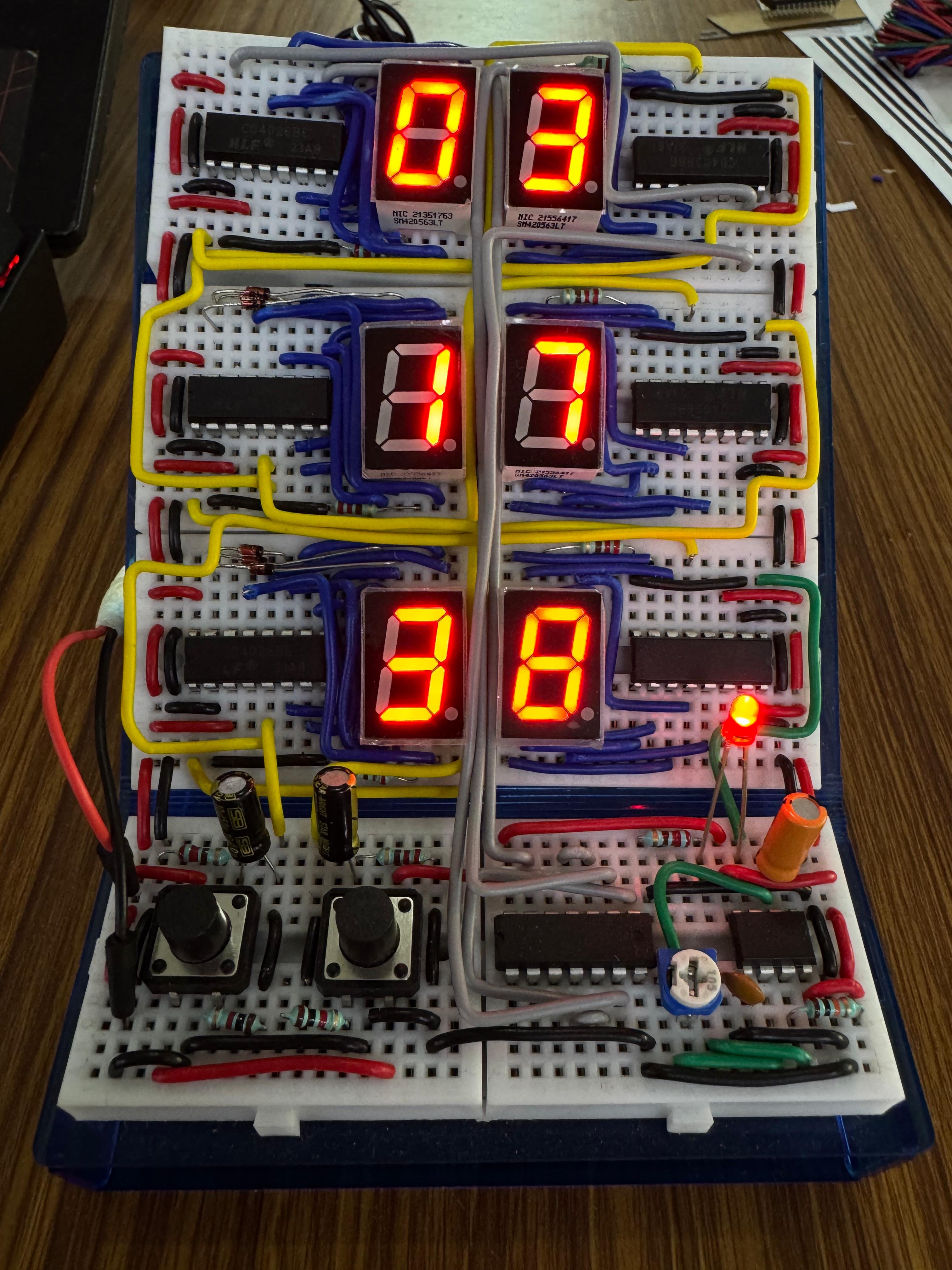
You've built a complete digital timekeeping device from scratch!
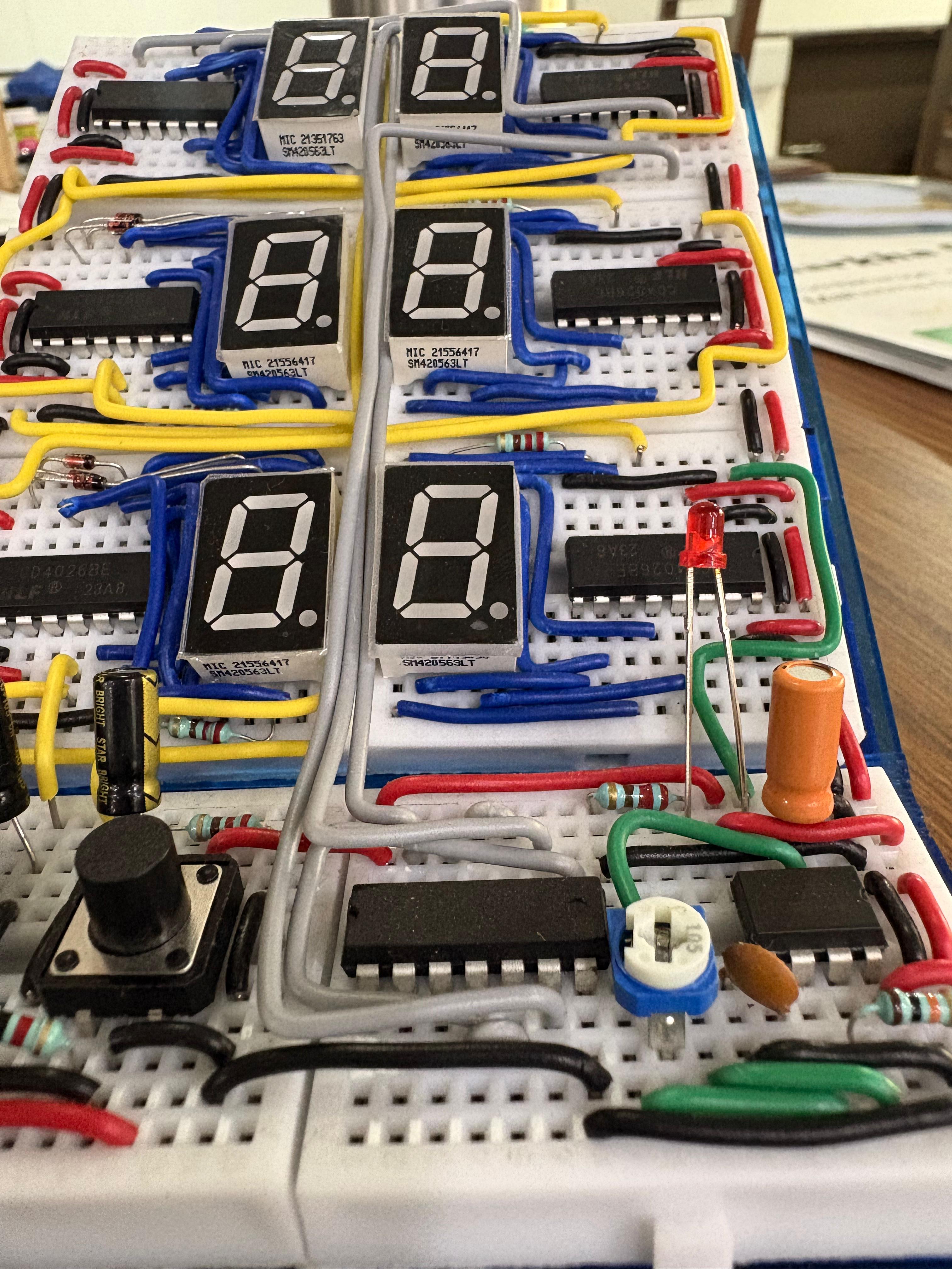
Your clock contains:
- 8 ICs performing different functions
- 6 displays with 42 total LED segments
- Over 100 connections all working together
- Multiple subsystems (timing, counting, reset, control)
You've applied concepts from both modules:
- Binary counting and BCD decoding (Module 1)
- Debouncing and clean signals (Module 2 Ex 1)
- Oscillators and timing circuits (Module 2 Ex 2)
- Reset logic and multi-digit detection (Module 2 Ex 3)
This project demonstrates fundamental concepts used in:
- Real digital clocks (same basic principle, just more integrated)
- Microcontrollers (timing and counting functions)
- Digital systems (cascading, reset logic, state machines)
13) Reflection Questions
14) Final Submission
Bonus: Also show the hours resetting from 11 to 00!
Reflect on your experience building this clock:
Congratulations on completing Module 1!
In Module 2, you'll learn about some fundamental blocks of modern digital logic and use them to make interesting circuits. You'll also understand how the Digital Clock you just made works in-depth!